Automatic cash transaction apparatus

A technology of automatic deposit and withdrawal and cash, which is applied to the accessories of ATMs, parts of ATMs, devices for accepting coins, etc., and can solve problems such as foreign objects entering

Inactive Publication Date: 2012-05-02
HITACHI OMRON TERMINAL SOLUTIONS CORP
View PDF5 Cites 27 Cited by
  • Summary
  • Abstract
  • Description
  • Claims
  • Application Information

AI Technical Summary

Problems solved by technology

In such a state, there is a possibility that the user mistakenly thinks that it is a banknote insertion po...

Method used


Image

  • Automatic cash transaction apparatus
  • Automatic cash transaction apparatus
  • Automatic cash transaction apparatus

Examples


Embodiment 1

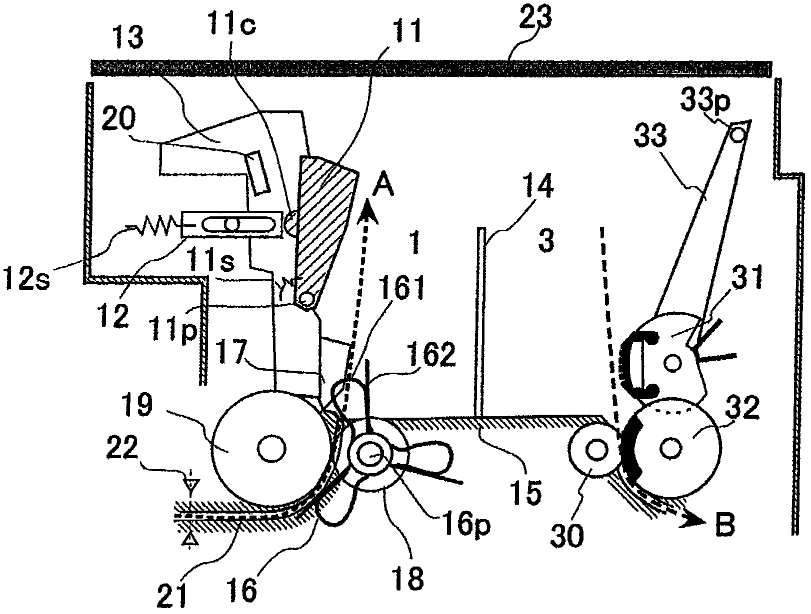
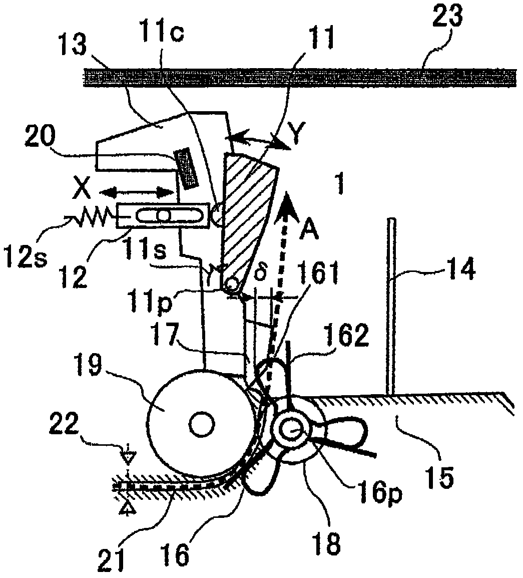
[0101] figure 1 It is a side view of the deposit and withdrawal slot which shows one Example of this invention.

[0102] exist figure 1 Among them, the actions of entering and exiting the banknotes include: during banknote deposit transactions, multiple banknotes dropped by the user are taken into the mechanism one by one for banknote separation; Banknote stacking operation for storing banknotes fed one by one.

[0103] First, the mechanism necessary for the separation operation will be described.

[0104] In order to perform the separation action, it includes: a delivery roller 32, which is used to send out the multiple banknotes dropped by the user one by one from the top; a resistance roller 30, opposite to the delivery roller 32, is used to prevent multiple banknotes from being sent out The feed roller 31 is used to feed the banknote into the banknote feeding part composed of the delivery roller 32 and the resistance roller 30; the action plate 14 is used to support t...


PUM


Abstract

The invention provides an automatic cash transaction apparatus, wherein paper-like articles are prevented from being poured into the apparatus and are regularly arranged to be accommodated. Therefore, foreign matters and the like will not block the cash inlet / outlet of the apparatus. The automatic cash transaction apparatus comprises a banknote discharge port used for users to take out banknotes; an accommodation space used for accommodating banknotes sheet by sheet; a guding member used for guiding banknotes; and sidewalls used for forming the accommodation space.

Description

technical field [0001] The present invention relates to an automatic cash deposit and withdrawal device having a stacking mechanism for stacking banknotes sent out from a conveyance path and a banknote deposit and withdrawal port for users to deposit and withdraw. Background technique [0002] In recent years, for the purpose of diversification of installation places and improvement of maintainability about an automatic teller machine, the downsizing of a mechanism and the increase of the number of banknotes which can be accommodated are being promoted. In addition, in order to achieve miniaturization and cost reduction, the simplification of the mechanism is also one of the important items of development. [0003] On the other hand, it is also necessary to be able to handle banknotes from all over the world. Banknotes of various countries in the world vary from small to large sizes by denomination. In addition, among banknotes of various countries in the world, there are ...

Claims


Application Information

Patent Timeline
IPC IPC(8): G07D11/00B65H29/22B65H29/52
CPCG07D11/14G07D11/17G07F19/201B65H29/22G07D2211/00
Inventor 三山敏史水野祥寺尾祐宣门胁稔
Owner HITACHI OMRON TERMINAL SOLUTIONS CORP
Why Eureka
Try Eureka