Kits for injection molding machines for molded parts

A technology for injection molding machines and molding parts, which is used in household components, applications, household appliances, etc., and can solve problems such as expensive machines

Active Publication Date: 2014-10-29
MOULIND
View PDF2 Cites 0 Cited by
  • Summary
  • Abstract
  • Description
  • Claims
  • Application Information

AI Technical Summary

Problems solved by technology

The above machines are expensive to purchase and maintain

Method used


Image

  • Kits for injection molding machines for molded parts
  • Kits for injection molding machines for molded parts
  • Kits for injection molding machines for molded parts

Examples


Embodiment Construction

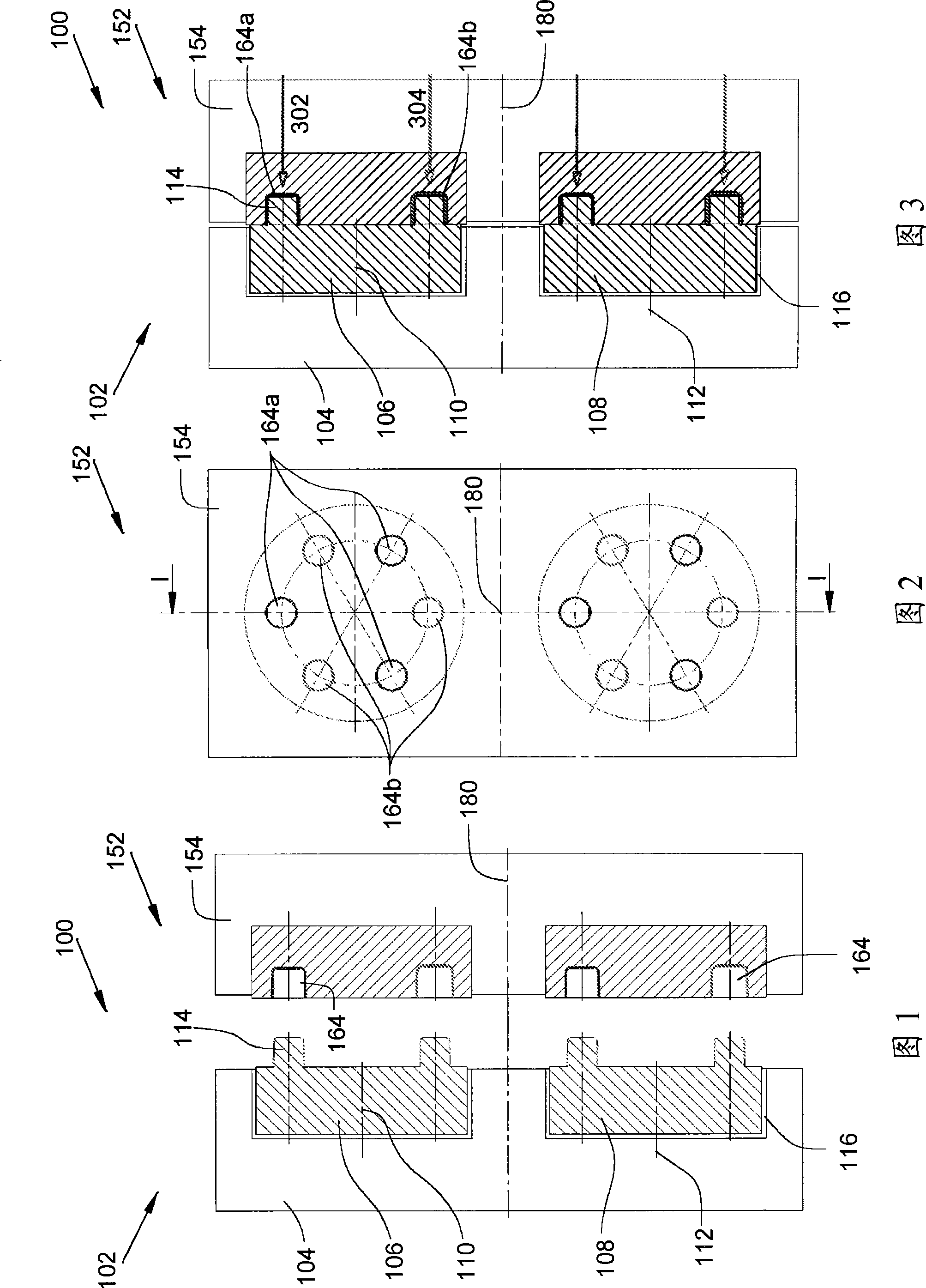
[0036] In the assembly in the figure, the kit is mounted on an injection molding machine connected to an injection press (not shown) which supplies the space defined by the cavity (empreinte) and the mating cavity (contre-empreinte). Molding material.

[0037] In the following description, the term "cavity" denotes a forming form provided on the cylindrical member, and the term "mating cavity" denotes an associated forming form complementary to said cavity. Accordingly, the molding cavities provided on the barrel may be referred to as "cavities" and "mating cavities". Forming cavities placed directly on the support plate are called "mating cavities".

[0038] The forming machine comprises a first platen and a second platen designed to be movable relative to each other by sliding in a translation direction 180 so as to be successively in an open state and a closed state.

[0039] figure 1 A kit 100 is shown for an injection molding machine for producing parts by molding and ...


PUM


Abstract

The invention concerns a kit for a machine for the injection moulding of moulded parts, the moulding machine comprising a first platen and a second platen, the kit comprising: a first support plate intended to be fixed to the said first platen; a second support plate intended to be fixed to the said second platen, the two platens being designed to be able to move with respect to each other by sliding so as to adopt successively an open position and a closed position; for the first support plate, at least one barrel of a first type, mounted so as to able to move in rotation on the said first support plate about an axis perpendicular to the plane of the said first support plate, and carrying at least two cavities; for the second support plate, at least one barrel of a second type, mounted so as to be able to move in rotation on said second support plate about an axis perpendicular to the plane of the said second support plate, and carrying at least two cavities.

Description

technical field [0001] The invention relates to a kit for an injection molding machine, the kit comprising at least one barrel, and an injection molding machine comprising such a kit. Background technique [0002] In order to mold multiple parts, such as receiver plugs, prior art injection molding machines include: a first plate carrying a plurality of first molding cavities on one of its surfaces; and a second plate carrying a plurality of first molding cavities on one of its surfaces A second molding cavity. Each first forming cavity is associated with a second forming cavity to form a space into which material is injected to produce the part to be formed. [0003] The two plates are movable relative to each other to slide between a closed state and an open state and in a direction of translation substantially normal to the plane of the two surfaces. [0004] In the closed state, the two surfaces are in contact with each other, so that the first forming cavity and the co...

Claims


Application Information

Patent Timeline
Patent Type & Authority Patents(China)
IPC IPC(8): B29C45/00B29C45/16
CPCB29C45/162B29C45/006B29L2031/565B29C2045/0063B29C2045/2689
Inventor 杰克·穆兰
Owner MOULIND
Why Eureka
Try Eureka