

Magnetic force driving mechanism for valve
A magnetic drive and valve technology, applied to engine components, valve operation/release devices, valve details, etc., can solve problems such as low safety, leakage, and production impact, and achieve the effect of improving production efficiency
- Summary
- Abstract
- Description
- Claims
- Application Information
AI Technical Summary
Problems solved by technology
Method used
Image

Examples
Embodiment Construction
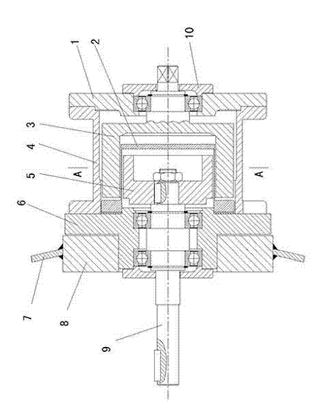
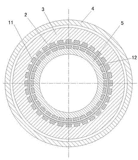
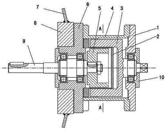
[0008] Such as figure 1 , 2 Shown: 9 is valve stem, is supported in the left end disk 6 by bearing, and left end disk 6 is fixedly connected with left bearing cover 13 by bolt. The left end plate 6 is connected to the right end plate 1 through the connecting sleeve 4, and the connecting sleeve 4, the left end plate 6 and the right end plate 1 are all fixedly connected by bolts. On the right end plate 1, the outer magnet cylinder 3 located inside the connecting sleeve 4 is supported by bearings, the shaft end of the outer magnet cylinder 3 protrudes to the outside of the right end plate 1, and the right end plate 1 is fixedly connected with a bolt with a right bearing cover 10 . There is an inner rotor 5 keyed to the valve stem 9 inside the outer magnet cylinder 3 , and a nut is provided at the end of the valve stem 9 for axially limiting the inner rotor 5 . An isolation cover 2 fixedly connected with the left end disk 6 is provided between the inner rotor 5 and the outer ma...
PUM
 Abstract
Description
Claims
Application Information