Method and device for reporting resource state in relay system

A technology of resource status and relay system, applied in the field of communication, can solve the problem of not being able to report the resource status, and achieve the effect of improving transmission efficiency and overall network performance.

Active Publication Date: 2012-05-09
DATANG MOBILE COMM EQUIP CO LTD
View PDF3 Cites 5 Cited by
  • Summary
  • Abstract
  • Description
  • Claims
  • Application Information

AI Technical Summary

Problems solved by technology

[0004] The resource status reporting schemes in the prior art are all designed for eNB. Since the interfaces between eNB and RN are different, the resource status reporting

Method used


Image

  • Method and device for reporting resource state in relay system
  • Method and device for reporting resource state in relay system
  • Method and device for reporting resource state in relay system

Examples


Example Embodiment

[0031] In the embodiment of the present invention, the relay device and the first base station integrate the resource status information of the Uu port and the Un port and send it to the second base station, thereby realizing the reporting of resource status information, so that the second base station can grasp the load situation of neighboring cells , Adjust the parameters such as handover and cell reselection, so as to enable load balancing in the network, improve transmission efficiency and overall network performance.
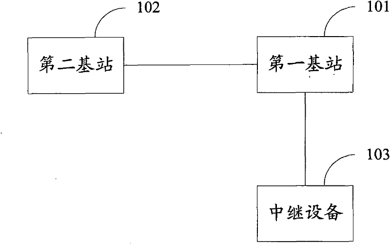
[0032] See figure 1 The communication system in this embodiment includes a first base station 101, a second base station 102, and a relay device 103. There is an X2 interface between the first base station 101 and the relay device 103, so the first base station 101 is a DeNB. There is an X2 interface between the second base station 102 and the first base station 101, but there is no direct interface with the relay device 103. It can have an interface with oth...


PUM


Abstract

The invention discloses a method for reporting a resource state in a relay system, which is used for realizing reporting of the resource state of relay equipment. The method comprises the following steps that: a first base station is used for forwarding a resource state report request sent by a second base station to the relay equipment; receiving resource state information sent by the relay equipment; and transmitting resource state information of a Uu port and a Un port to the second base station. The invention also discloses a device for realizing the method.

Description

technical field [0001] The invention relates to the communication field, in particular to a method and device for reporting resource status in a relay system. Background technique [0002] In the LTE-A (Long Term Evolution-Advanced, upgraded long-term evolution) system, a relay node (Relay Node, hereinafter referred to as RN) is introduced in order to improve system throughput and increase network coverage. The RN is connected to a base station (Donor Evolved Node B, DeNB) in a wireless manner. The interface between UE and RN is called Uu interface, and the interface between RN and DeNB for data transmission is called Un interface. see figure 1 As shown, the RN is indirectly connected to other base stations (eNBs) through its own DeNB. And the cells under the RN may be adjacent to the cells under other base stations. Wherein, the base station connected to the RN is called a DeNB, and the DeNB is a kind of eNB. [0003] In a Long Term Evolution (LTE) network, for the pur...

Claims


Application Information

Patent Timeline
IPC IPC(8): H04W28/08H04L1/18H04L1/00
CPCH04B7/15542H04W24/10
Inventor 刘佳敏张大钧
Owner DATANG MOBILE COMM EQUIP CO LTD
Why Eureka
Try Eureka