Method for determining an effect of a particle beam on a material

A particle beam and action technology, applied in X-ray/γ-ray/particle irradiation therapy, radiation/particle treatment, radiation therapy, etc., can solve the problem of not being able to provide radiation planning

Active Publication Date: 2014-11-05
GSI HELMHOLTZZENT FUR SCHWERIONENFORSCHUNG
View PDF0 Cites 0 Cited by
  • Summary
  • Abstract
  • Description
  • Claims
  • Application Information

AI Technical Summary

Problems solved by technology

[0011] So far known models do not provide sufficiently precise information for radiation planning over the entire range from light to heavy ions

Method used


Image

  • Method for determining an effect of a particle beam on a material
  • Method for determining an effect of a particle beam on a material
  • Method for determining an effect of a particle beam on a material

Examples


Embodiment Construction

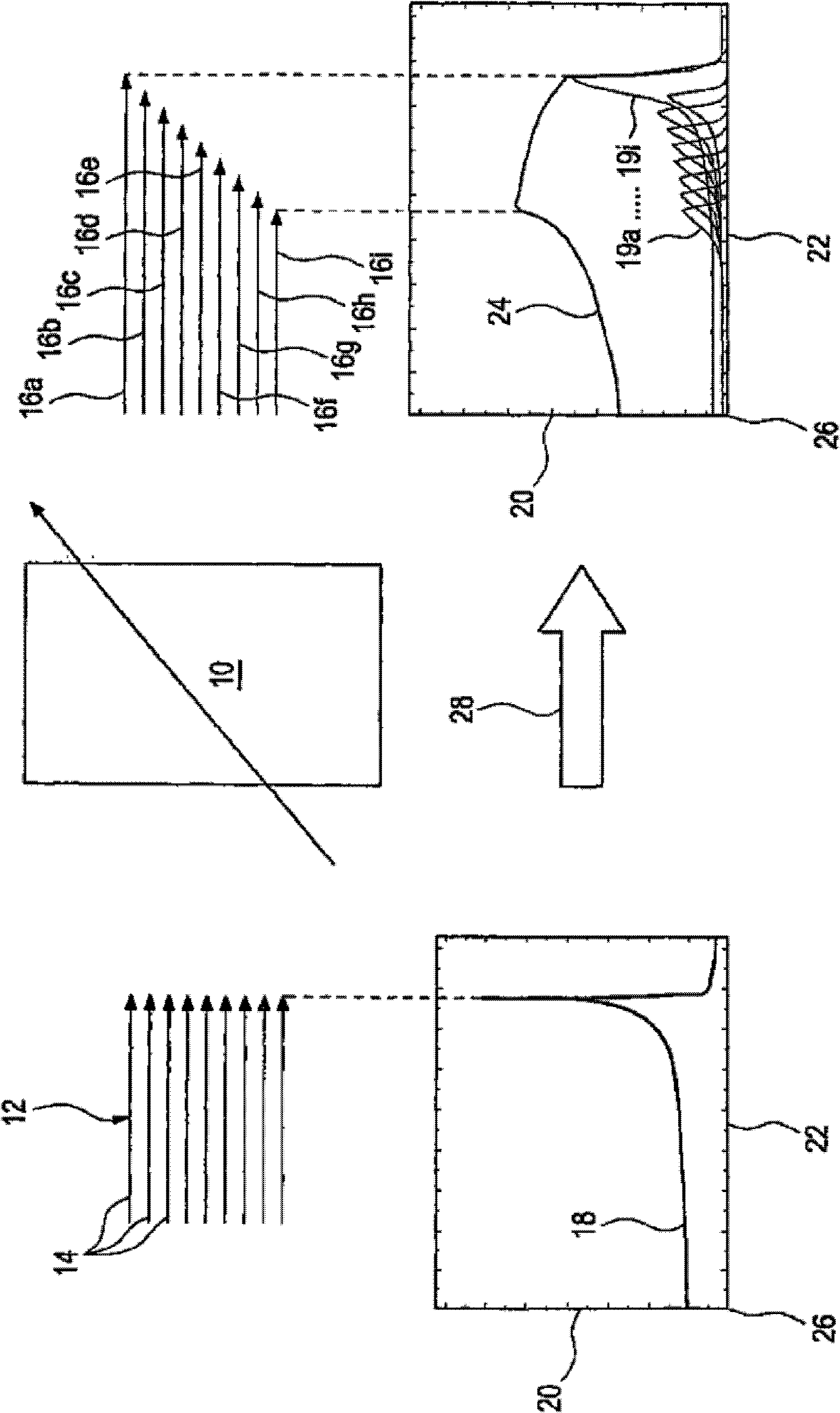
[0110] figure 1 A beam conditioning device 10 and its effect on a monoenergetic ion or particle beam 12 is shown schematically. The monoenergetic ion beam 12 is shown schematically using arrows 14 of equal length. Arrows 16a to 16i represent ion beams of different energies and thus ion beams 16 that are not monoenergetic, ie have ions of different energies. exist figure 1 The lower part of , each showing a diagram in a schematic manner. It represents the Bragg peak 18' (shown on the left), 24 (shown on the right) in the material to be irradiated (not shown), which shows the relative dose as a function of the penetration depth in the material. The relative dose is plotted on an axis 20 called the y-axis, and the penetration depth is plotted on an axis 22 called the x-axis. The variation of the curve of the Bragg peak 18 describes the variation of the dose as a function of the depth of irradiation with monoenergetic ions. The Bragg peak 24 describes the relative dose in the...


PUM


Abstract

The method involves partial determining the effect of a particle beam on the material based on a microscopic damage correlation from a parameter and from a property of the material. The parameter characterizes the particle beam. The microscopic damage correlation takes place in sub micrometer range. Independent claims are also included for the following: (1) a method for the radiation planning for a target volume in a radiation volume by a particle radiation; (2) a method for radiation of the target volume in the radiation volume by a particle radiation; (3) a radiation planning for the radiation volume; (4) a radiation planning device with a computer unit for executing the method; and (5) a beam modification device for a radiation device.

Description

technical field [0001] The invention relates to a method for determining the effect of a particle beam in at least partially irradiated material or material to be irradiated, a radiation planning method for irradiating a target volume and a method for irradiating a target volume with a particle beam, radiation planning, beam conditioning device and radiation equipment. Background technique [0002] Irradiating a target volume in an irradiation volume with an ion beam or particle beam involves the irradiation of matter, in particular inorganic, organic and biological materials, and is used in various fields of research, industry and medical engineering. The target volume notably includes regions where a predetermined dose is to be deposited to modify the irradiated material; the irradiated volume notably also includes those regions of the material which are penetrated by radiation to achieve the desired dose in the target volume. A "particle beam" or "ion beam" is understood...

Claims


Application Information

Patent Timeline
Patent Type & Authority Patents(China)
IPC IPC(8): A61N5/10
CPCA61N2005/1087G21K1/10A61N5/1031
Inventor M.肖尔茨T.埃尔萨泽
Owner GSI HELMHOLTZZENT FUR SCHWERIONENFORSCHUNG
Why Eureka
Try Eureka