
Radiation therapy planning optimization and visualization

A technology for delivery planning and planning, applied in the direction of mechanical/radiation/invasive therapy, therapy, radiotherapy, etc.

Active Publication Date: 2019-07-26
KONINKLJIJKE PHILIPS NV
View PDF7 Cites 0 Cited by
  • Summary
  • Abstract
  • Description
  • Claims
  • Application Information

AI Technical Summary

Problems solved by technology

In other words, it is often unclear to the planner what changes in the inputs can produce meaningful differences

Method used


Image

  • Radiation therapy planning optimization and visualization
  • Radiation therapy planning optimization and visualization
  • Radiation therapy planning optimization and visualization

Examples


Embodiment Construction

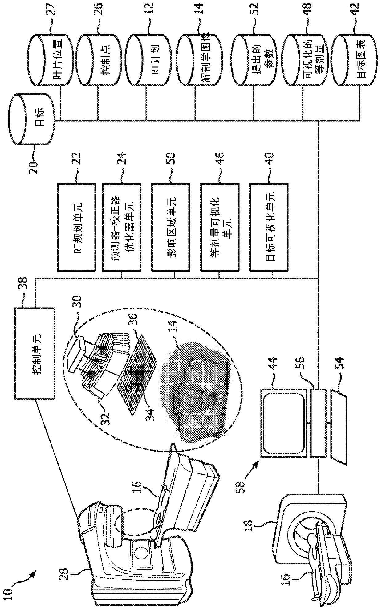
[0033] refer to figure 1, schematically illustrates an embodiment of a radiation delivery planning optimization and visualization system 10 with an exploded view of radiation delivery. A radiation therapy (RT) or radiation delivery plan 12 is constructed based on anatomical or internal planning images 14 of a subject 16 acquired from an imaging device 18 such as a CT imaging device, MRI imaging device, or the like. The planning image 14 identifies a region of interest (ROI), which includes one or more targets and the boundaries of the OAR, and is used to determine a three-dimensional density distribution that allows calculation of dose. The RT planning target 20 can reference or store ROIs, weights, and other target type specific parameters like reference dose as input parameters to the inverse planning unit or device 22 that creates the RT plan.

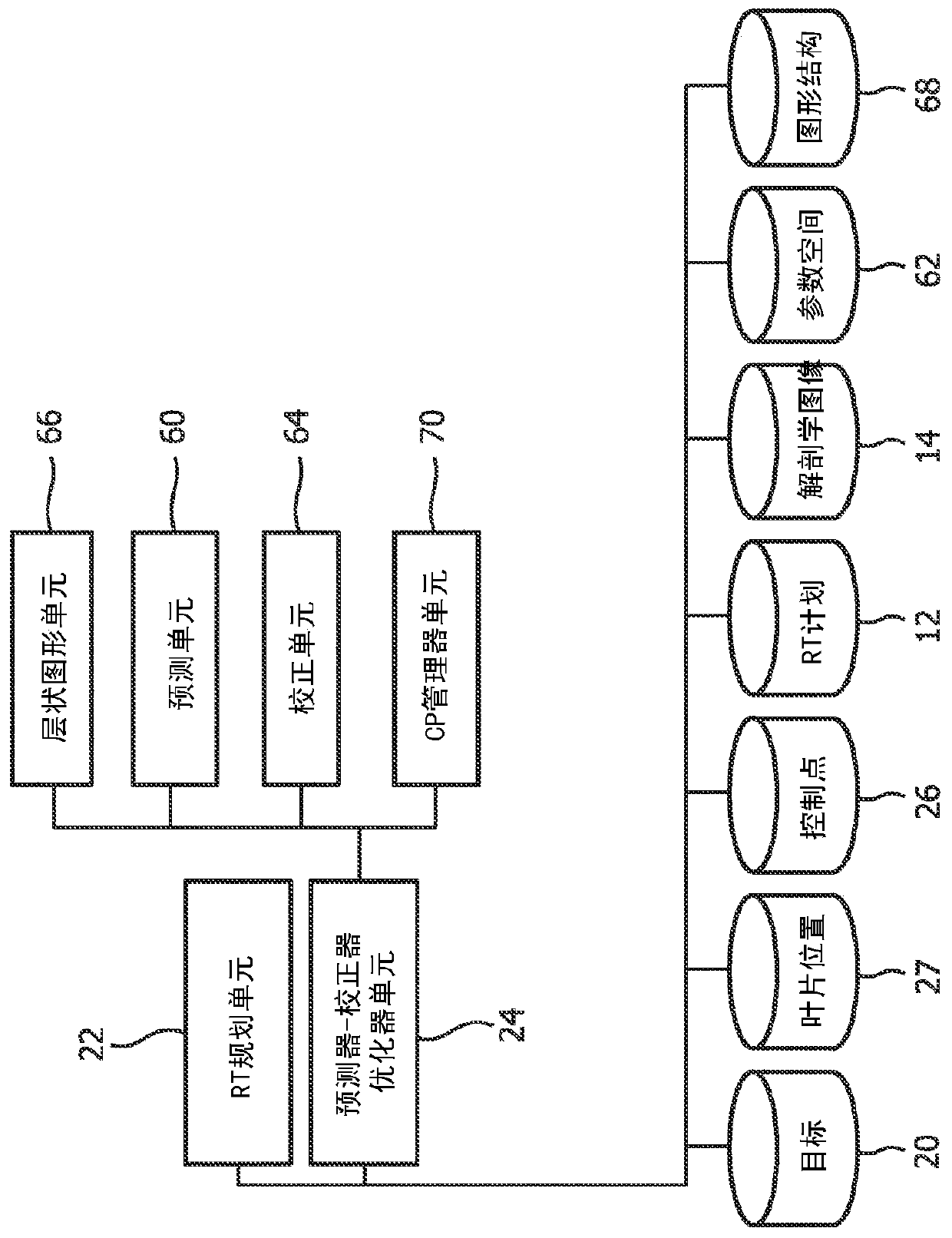
[0034] Within the RT planning unit 22, a predictor-corrector optimizer unit or device 24 receives the planning target, a set of c...


PUM


Abstract

A radiation planning system comprising: a predictor-corrector optimizer unit that calculates a predicted dose based on a collection of control points with a current approaching dose, each control point having a corresponding set of blade positions, and based on The difference between the predicted flux and the current approximating flux of the lowest cost or shortest path in the layered graph structure in the achieved blade positions is used to determine additional control points with sets of blade positions. The tool is described as assisting planners in evaluating the impact of parameter changes on current plans based on identified areas of impact. The planner views the current plan based on the visualization of the plan objectives and dependencies between the objectives.

Description

technical field [0001] The following generally refers to external radiation therapy planning. It finds particular application in connection with radiation therapy plan construction, optimization and visualization and will be described with particular reference thereto. However, it should be understood that it is also applicable to other usage scenarios and is not necessarily limited to the aforementioned applications. For example, the following can be used to deliver selected radiation doses to target areas in various industrial applications (e.g. disinfection, burning of polymers, altering electrical, mechanical or chemical properties, etc.), even without physical access To selected areas of industrial products including interior areas. Background technique [0002] External Beam Radiation Therapy (EBRT) plans are constructed based on the machine characteristics of the Linear Particle Accelerator (LINAC) and information from each individual patient. A plan is created for...

Claims


Application Information

Patent Timeline
Patent Type & Authority Patents(China)
IPC IPC(8): A61N5/10
CPCA61N5/103A61N5/1036A61N5/1031G16H20/40G16H50/30G16H20/10A61N5/1039A61N5/1045
Inventor T·维克H·S·黑泽D·贝斯特罗夫J·威斯C·诺伊基兴A·A·伊索拉M·F·巴尔
Owner KONINKLJIJKE PHILIPS NV
Learn More