Flexible, abrasion resistant textile sleeve and method of construction thereof

A technology for sleeves and fabrics, applied in the direction of fabrics, woven fabrics, textiles and papermaking, etc., can solve the problems of rising costs and achieve the effect of low manufacturing costs and enhanced protection

Active Publication Date: 2012-05-16
FEDERAL MOGUL POWERTRAIN INC
View PDF9 Cites 25 Cited by
  • Summary
  • Abstract
  • Description
  • Claims
  • Application Information

AI Technical Summary

Problems solved by technology

However, the need for a tighter weave often results in higher costs

Method used


Image

  • Flexible, abrasion resistant textile sleeve and method of construction thereof
  • Flexible, abrasion resistant textile sleeve and method of construction thereof
  • Flexible, abrasion resistant textile sleeve and method of construction thereof

Examples


Embodiment Construction

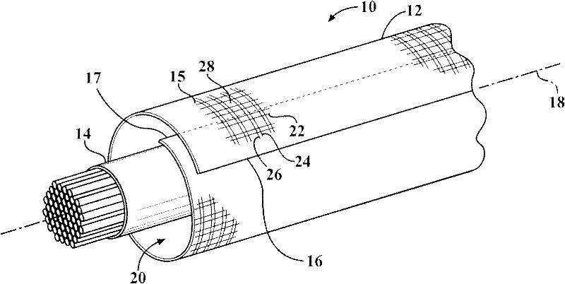
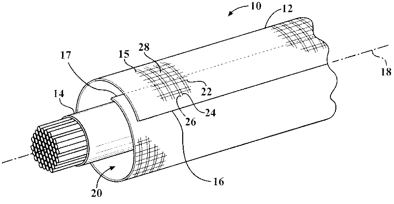
[0013] Referring more specifically to the drawings, FIG. 1 is a schematic illustration of a braided self-wrapping fabric sleeve, hereafter shown as sleeve 10 , constructed in accordance with one aspect of the present invention. The sleeve 10 has an elongated wall 12 for guiding and protecting the self-wrapping of an elongated element such as an electrical wire or harness 14, for example to protect the elongated element from wear and from the ingress of contaminants, debris, etc. . The elongated wall 12 has opposing edges 16, 17 extending generally parallel to the central longitudinal axis 18, wherein the edges 16, 17 are preferably deflected to overlap each other to wrap the elongated member 14 in a "cigarette wrapped" fashion. It is completely enclosed in the central cavity 20 of the sleeve. The cavity 20 can extend the entire length of the longitudinal axis 18, so that the elongated element 14 can be easily placed radially within the cavity 20 and, conversely, can be easily...


PUM


Abstract

A textile sleeve for routing and protecting elongate members and method of construction thereof is provided. The sleeve includes an elongate wall having opposite edges extending parallel to a central axis of the sleeve. The wall is woven with warp yarns extending parallel to the axis and fill yarns extending transverse to the warp yarns. The warp yarns are provided as monofilament yarns to provide abrasion resistance and the fill yarns are provided as both monofilament yarns to provide further abrasion resistance and multifilament yarns to provide increased coverage, maintain flexibility, and to maintain the warp monofilaments in their intended position.

Description

[0001] Cross References to Related Applications [0002] This application claims the benefit of US Provisional Application Serial No. 61 / 186,174, filed June 11, 2009, which is hereby incorporated by reference in its entirety. technical field [0003] The present invention relates generally to fabric sleeves for protecting elongate elements, and more particularly to braided sleeves. Background technique [0004] It is known, for example in automobiles, aircraft or spacecraft, that electrical wires and harnesses are encased in protective sleeves to protect the electrical wires from abrasion, fluid and temperature. To achieve the desired protection, the protective sleeve may have multiple layers, some of which are specific for different types of protection. For example, one layer is used for water resistance (such as a plastic sheet), while another layer is used for abrasion resistance, and yet another layer is used for resistance to thermal environments (such as a non-woven ...

Claims


Application Information

Patent Timeline
Patent Type & Authority Applications(China)
IPC IPC(8): D02G3/38D03D15/00
CPCD03D1/0041D03D3/02D10B2401/04D10B2331/301H02G3/0481B60R16/0215D03D15/00D10B2331/04D03D3/08D03D1/0043D03D15/50D03D15/283D03D13/00D10B2401/063D03D15/56
Inventor 惠美·柏原
Owner FEDERAL MOGUL POWERTRAIN INC
Why Eureka
Try Eureka