
fume hood

A technology for exhaust hoods and outer covers, applied in the field of exhaust hoods, which can solve problems such as difficult access to connection positions, difficult manufacturing, and complicated manufacturing, and achieve the effect of reducing the number

Inactive Publication Date: 2015-08-19
BSH BOSCH & SIEMENS HAUSGERAETE GMBH
View PDF7 Cites 0 Cited by
  • Summary
  • Abstract
  • Description
  • Claims
  • Application Information

AI Technical Summary

Problems solved by technology

[0006] The disadvantage of known fume extraction hoods in the form of chimneys is that a great variety of components is required in order to be able to realize different shapes of the fume extraction hood, in particular of the sight housing and of the ventilation box
Furthermore, the manufacture is complicated due to the large number of connection points and difficult due to the inaccessibility of parts of the connection points

Method used


Image

  • fume hood
  • fume hood
  • fume hood

Examples


Embodiment Construction

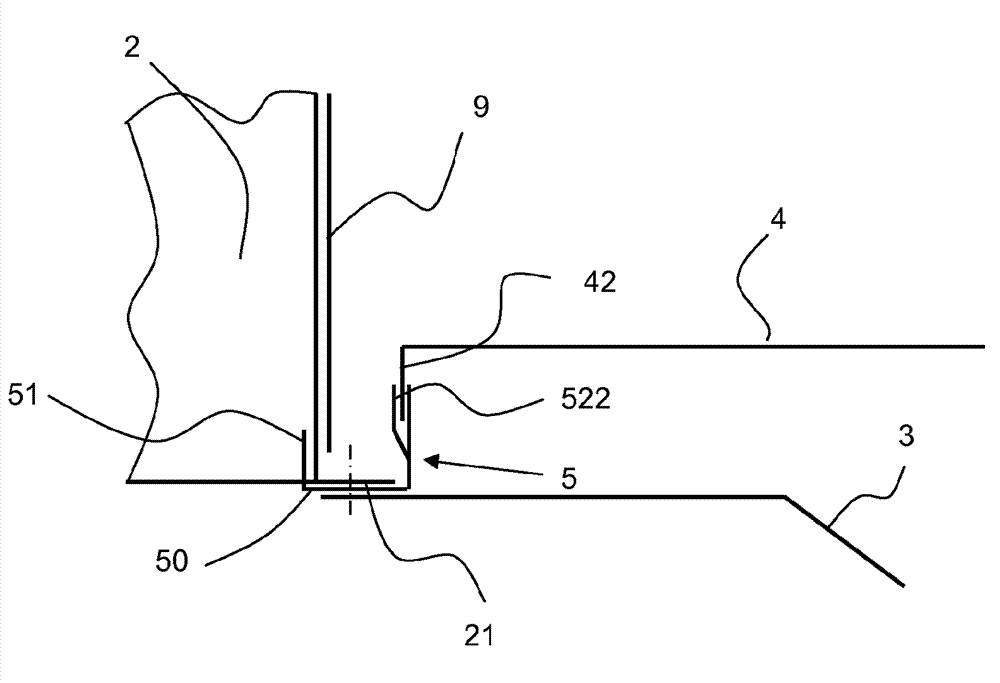
[0040] exist figure 1 The embodiment of the fume extraction hood 1 according to the invention shown in has a ventilation box 2 which comprises a box-shaped base body 20 and which comprises a flange 21 at its bottom side on the side which extends from the base body 20 The sides extend outward respectively. Furthermore, the fume extraction hood 1 has an inner frame 3 which is connected on its upper side to the ventilation box 2 , in particular to a flange 21 . The inner frame 3 has a channel-shaped base body 32 . A rectangular air passage 33 is provided in the bottom of the base body 32 .

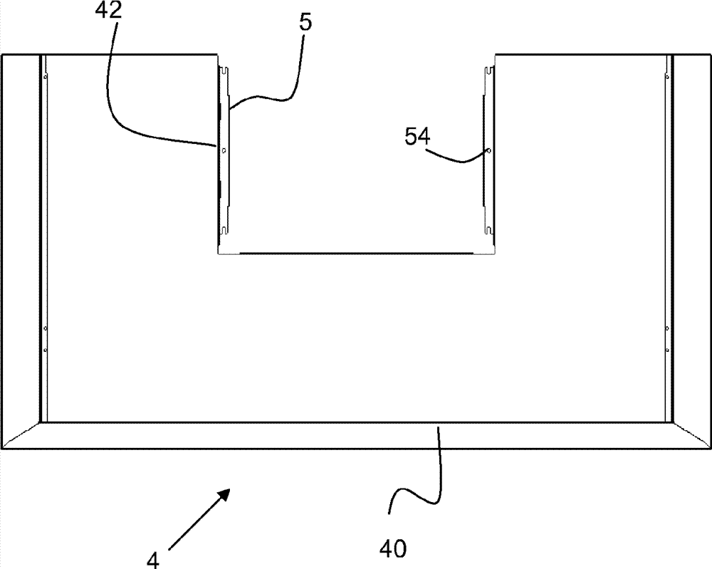
[0041] Furthermore, the fume extraction hood 1 comprises a visible cover 4 which is fixed on a base frame consisting of the ventilation box 2 and the inner frame 3 . On the upper side, the visibility cover 4 has a rectangular recess extending from the rear, the dimensions of which correspond at least to the dimensions of the underside of the ventilation box 2 . On the inner side of the re...


PUM


Abstract

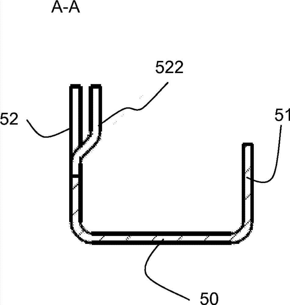
The invention relates to an extractor hood comprising an extractor box (2), an inner frame (3) and a capture panel (4). Said extractor hood (1) is characterised in that at least one fastening rail (5) is provided on said extractor box (2), said fastening rail comprising at least one connection area (521, 522) for detachably connecting to the capture panel (4).

Description

technical field [0001] The invention relates to a fume exhaust hood. Background technique [0002] It is known that in the case of fume extraction hoods designed as so-called chimneys, the actual housing is fastened in a ventilation box, which can also be referred to as a ventilation housing. The housing is bounded upwards and outwards in the chimney by a visible housing, and functional elements, such as electronic components, are housed in the housing. Furthermore, a filter element is held in the housing, which covers the intake opening of the fume extraction hood. Above the hood, the ventilation box is covered by the flue. [0003] Such chimneys are currently manufactured in such a way that the sight housing is screwed to the ventilation box. Furthermore, the reinforcing and connecting elements are screwed to the sight housing in order to give it the necessary rigidity and to be able to fix the functional element and the filter element thereon. Thus, for example, in th...

Claims


Application Information

Patent Timeline
IPC IPC(8): F24C15/20
CPCF24C15/2071
Inventor J.莱斯M.里希特A.施维尔
Owner BSH BOSCH & SIEMENS HAUSGERAETE GMBH
Learn More