Air flow direction changing device for air adjusting device

A technology of wind direction change and air conditioning, which is applied in the field of air conditioning devices, can solve problems such as the unsatisfactory air supply performance of horizontal blades, and achieve the effect of improving air supply performance

Inactive Publication Date: 2012-05-23
SHARP KK
View PDF10 Cites 11 Cited by
  • Summary
  • Abstract
  • Description
  • Claims
  • Application Information

AI Technical Summary

Problems solved by technology

[0007] However, in Patent Document 2, only the air supply structure between the auxiliary plate and the guide plate is improved, and it is not expected to use horizontal blades (horizontal louvers) to improve the air supply performance of blowing air to farther places.

Method used


Image

  • Air flow direction changing device for air adjusting device
  • Air flow direction changing device for air adjusting device
  • Air flow direction changing device for air adjusting device

Examples


Embodiment Construction

[0063] Embodiments of the present invention will be described below based on the drawings. In this embodiment, an indoor unit of a separate air conditioner as an example of an air conditioner will be described as an example. This air conditioner utilizes refrigerant pipes to connect the heat exchanger housed inside the indoor unit and the compressor housed in the outdoor unit (not shown), a four-way valve, an outdoor heat exchanger, and a throttling device (not shown). shown) to form a refrigeration cycle system, so that various operating modes such as cooling, heating, and dehumidification can be performed.

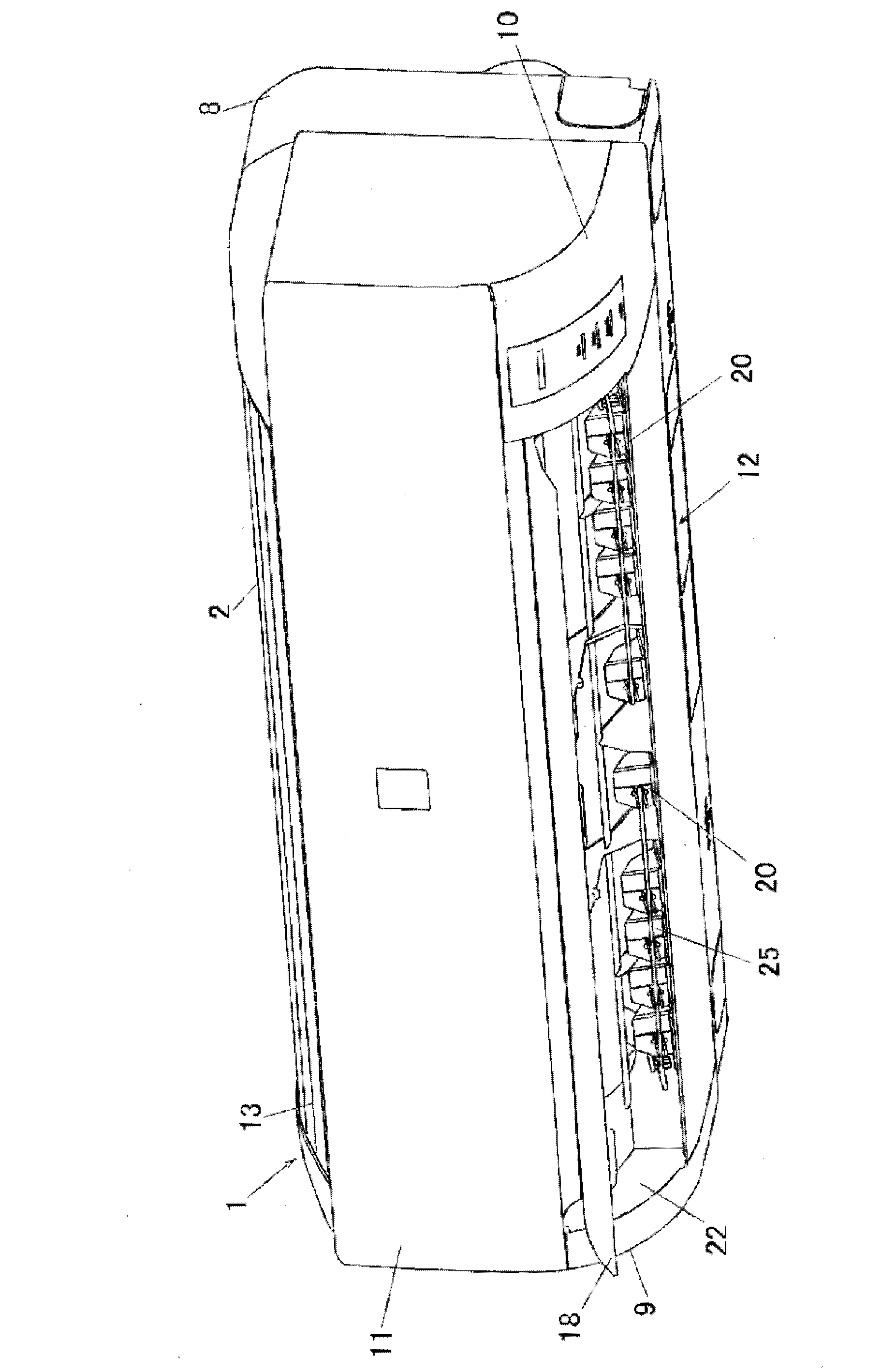
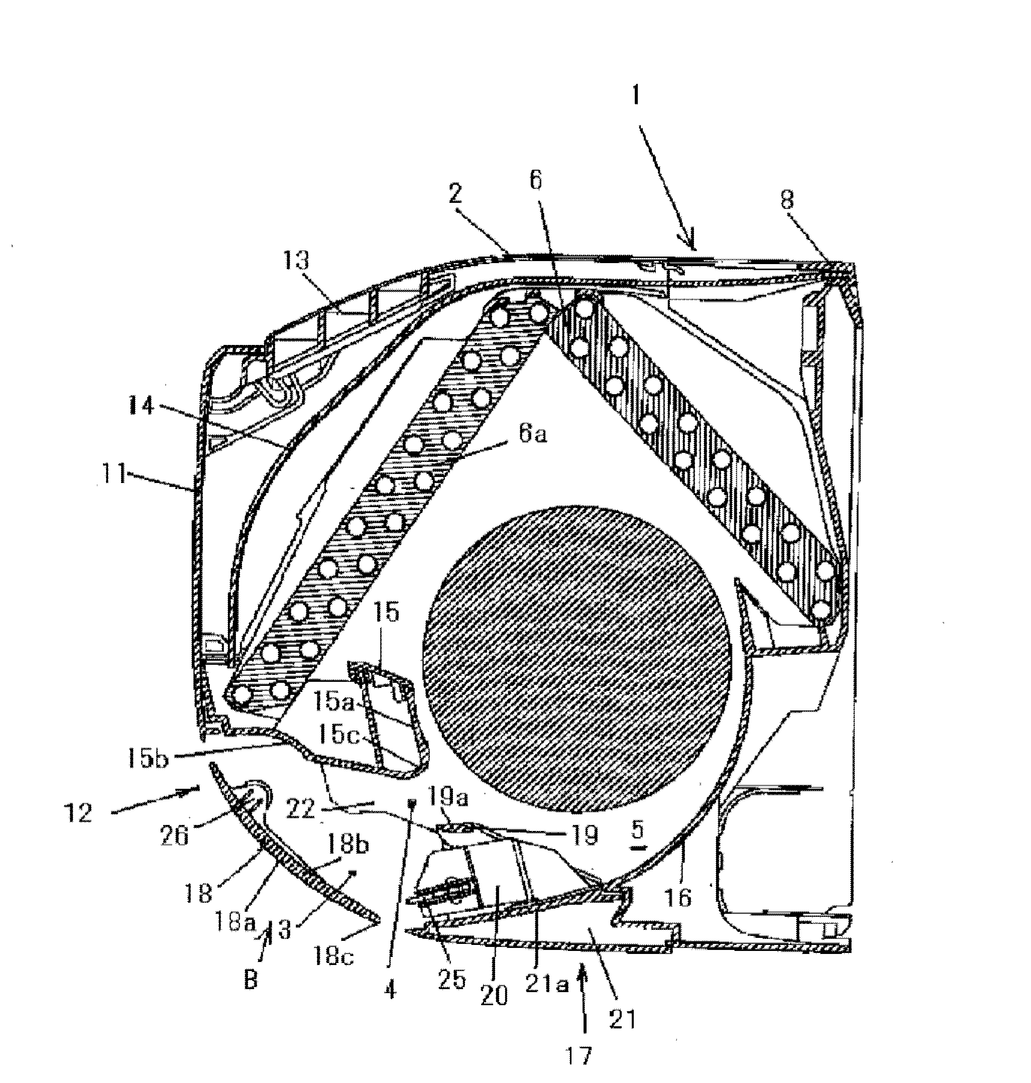
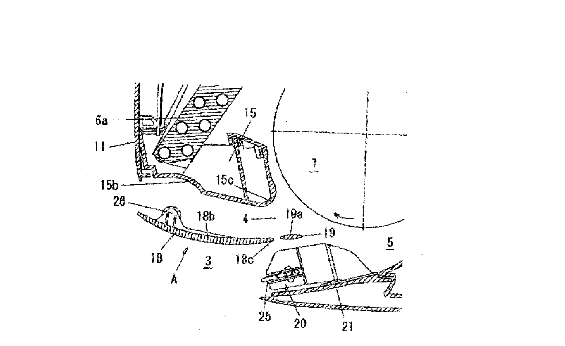
[0064] Such as figure 2As shown, the indoor unit is formed with a suction port 2 on the upper surface of the casing 1 for sucking indoor air, and an outlet 4 is formed on the opening 3 below the front surface of the casing 1 . An air passage 5 is formed inside the casing 1 from the suction port 2 to the blowing port 4 , and a heat exchanger 6 and a fan 7 are disposed ...


PUM


Abstract

An air flow direction changing device for an air adjusting device is provided with: a horizontal louver pivotably provided in front of the air discharge opening of the cabinet; a control unit for pivotably driving and controlling at the front face of the air discharge opening the horizontal louver and changing the discharge direction of the air flow delivered from the fan; and a flow regulating plate provided behind the pivoting range of the horizontal louver and regulating the air flow from the fan located at the rear of an air flow path. The control unit improves the air delivery performance by controlling the pivoting position of the horizontal louver in order that an air delivery guide path having a length greater than the depth of the single horizontal louver is formed, the air delivery guide path being formed by cooperation between the upper surface of the horizontal louver and the upper surface of the flow regulating plate when the horizontal louver is in an upwardly discharging position.

Description

technical field [0001] The present invention relates to an air conditioner provided with a wind direction changing device capable of changing the direction of the wind blown out from an air outlet of a casing. Background technique [0002] In the air conditioner, when controlling the wind direction of the air duct, the wind guide panel or the auxiliary louver is controlled. The air guide panel is close to the air outlet near the rear (refer to Patent Document 1), but since the air guide panel and the auxiliary louvers are arranged near the air outlet and controlled independently, the length of the auxiliary louvers and the air guide panel Air blowing performance is affected, and it is difficult to improve blowing performance by combining both in an air-conditioning apparatus that is trying to achieve compactness and cost reduction. [0003] Therefore, in order to improve the air blowing performance by using either the panel structure or the auxiliary louvers, as another met...

Claims


Application Information

Patent Timeline
Patent Type & Authority Applications(China)
IPC IPC(8): F24F13/14F24F13/08F24F13/20
CPCF24F2001/0048F24F1/0011F24F1/0057F24F13/1486F24F13/30F24F2221/17
Inventor 山崎良信
Owner SHARP KK
Why Eureka
Try Eureka