
Single-handle hand riveter

A riveting gun and handle-type technology is applied in the field of single-hand riveting guns to achieve the effect of convenient use

Active Publication Date: 2012-05-30
YUYAO TANGWEN TOOL CO LTD
View PDF8 Cites 7 Cited by
  • Summary
  • Abstract
  • Description
  • Claims
  • Application Information

AI Technical Summary

Problems solved by technology

[0005] The problem to be solved by the embodiments of the present invention is to provide a single-handle riveting gun to overcome the fact that in the prior art, the riveting requires the user to use a lot of force to complete the riveting due to the fact that the upward torque of the prying rod remains unchanged. Defects

Method used


Image

  • Single-handle hand riveter
  • Single-handle hand riveter
  • Single-handle hand riveter

Examples


Embodiment 1

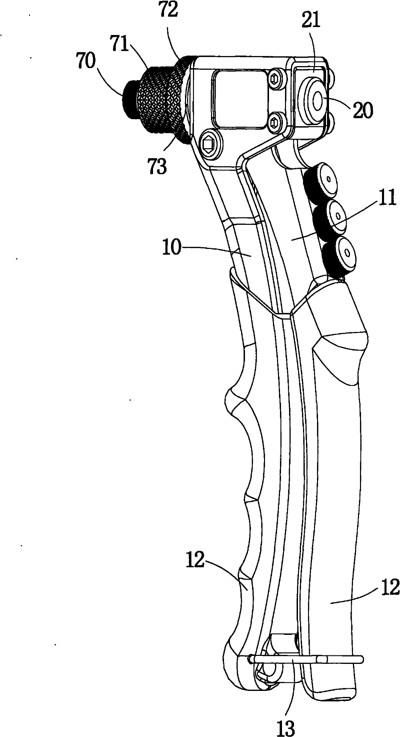
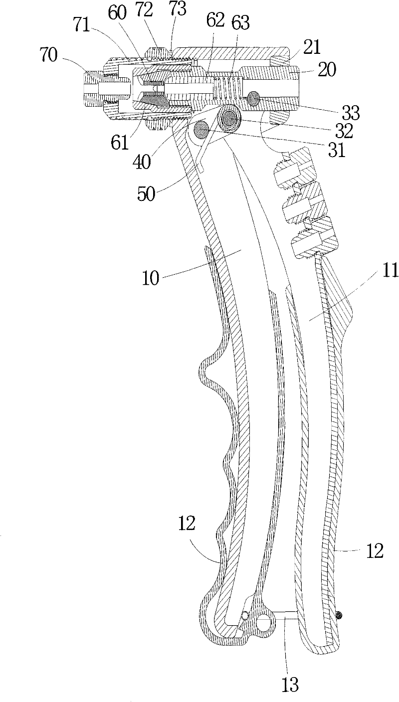
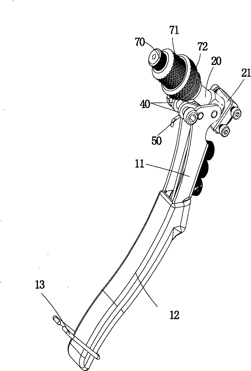
[0026] The structure of a kind of single type riveting gun of the embodiment of the present invention is as figure 1 , figure 2 with image 3 As shown, it includes a body 10, a handle 11, a pull rod 20, a gripping mechanism, and a rivet adjustment mechanism, as well as a first pin 31, a second pin 32, a third pin 33, and a link piece 40; the rivet adjustment mechanism Cooperate with the front end of the body 10; the gripping mechanism is arranged in the cavity of the rivet adjustment mechanism, and its tail part is matched with the pull rod 20; the first pin shaft 31 is fixed on the body 10; the The second pin shaft 32 is fixed on the handle 11 and connected to the first pin shaft 31 through the link piece 40 ; the third pin shaft 33 is fixed on the handle 11 and fixedly connected to the pull rod 20 at the same time. The positional relationship between the first pin 31, the second pin 32 and the third pin 33 and the pull rod 20 is as follows: Figure 4 As shown, when the r...

Embodiment 2

[0034] The described rivet adjustment mechanism can also have other structures. For example, a rivet opening with the same size as the rivet outlet in the rivet guide nozzle 70 can be set on the adjustment sleeve 71, so that the rivet guide nozzle 70 is no longer needed, and the riveting stroke can be changed by adjusting the adjustment sleeve 71 , it is also very convenient to use. All the other are the same as embodiment one.

[0035] The single handle riveting gun of the present invention uses three pins to connect the body, the handle and the pull rod, and the second pin fixed on the handle is connected to the first pin fixed on the body through the connecting plate, and is fixed on the handle The third pin shaft is fixed on the pull rod at the same time; when riveting, the second pin shaft is driven by the link plate to approach the pull rod, so that the torque is increased, so that the use is more labor-saving. In addition, in the single-handle riveting gun of the pres...


PUM


Abstract

The invention discloses a single-handle hand riveter. The hand riveter comprises a body, a handle, a pull rod, a grasping mechanism, a rivet adjusting mechanism, a first hinge pin, a second hinge pin, a third hinge pin and a linkage plate, wherein the rivet adjusting mechanism is matched with the front end of the body; the grasping mechanism is arranged in the chamber of the rivet adjusting mechanism; the tail of the grasping mechanism is matched with the pull rod; the first hinge pin is fixed on the body; the second hinge pin is fixed on the handle and is connected with the first hinge pin by the linkage plate; and the third hinge pin is fixed on the handle and is simultaneously connected on the pull rod fixedly. The single-handle hand riveter has the following advantages that the three hinge pins are adopted to be connected with the body, the handle and the pull rod, the second hinge pin fixed on the handle is connected with the first hinge pin fixed on the body by the linkage plate and the third hinge pin fixed on the handle is simultaneously fixed on the pull rod; and during riveting, the second hinge pin is driven by the linkage plate to approach the pull rod so that the moment is increased, thus further saving labor during use.

Description

technical field [0001] The invention relates to the technical field of riveting tools, in particular to a single-handle riveting gun. Background technique [0002] Riveting guns are used for the fastening and riveting of various types of metal sheets, pipes and other manufacturing industries. At present, they are widely used in the riveting of electromechanical and light industrial products such as automobiles, aviation, railways, refrigeration, elevators, switches, instruments, furniture, and decoration. , mainly to solve the shortcomings of metal sheets and thin tubes that weld nuts are easy to melt, and tapping internal threads is easy to slip. It can rivet riveting products that do not require tapping internal threads and welding nuts. The riveting is firm and efficient, and it is easy to use. If the nuts of a certain product need to be installed on the outside, but the inside space is too small to allow the indenter of the riveting machine to enter for riveting and the ...

Claims


Application Information

Patent Timeline
IPC IPC(8): B21J15/38
CPCB21J15/38B21J15/386Y10T29/53757Y10T29/5373B21J15/105
Inventor 袁建明
Owner YUYAO TANGWEN TOOL CO LTD
Learn More