[0025] The specific embodiments of the present invention will be described in further detail below in conjunction with the drawings and embodiments. The following examples are used to illustrate the present invention, but not to limit the scope of the present invention.
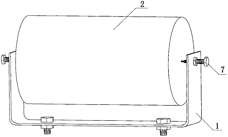
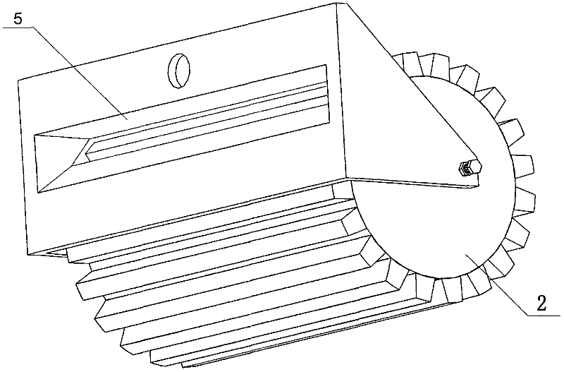
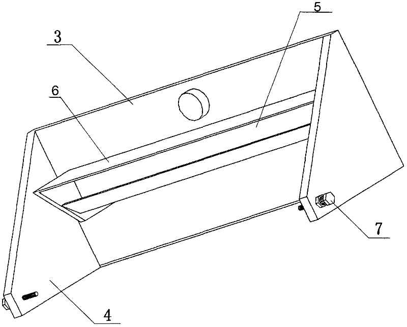
[0026] Such as figure 1 with figure 2 As shown, the present invention provides a casing conveying device, which includes several horizontal conveying units arranged in parallel. The conveying unit includes a bracket 1, a roller 2 and an air supply unit (not shown). The roller 2 is rotatably fixed on the bracket 1. Above, the surface of the roller 2 is smooth, and can also be provided with grooves or flanges along its width. Such as image 3 As shown, the support 1 is composed of a bottom plate 3 and vertical baffles 4 located on both sides of the bottom plate 3. The bottom plate 3 is provided with a tuyere 5, which is arranged within the radius of the roller 2, and the tuyere 5 is parallel to the central axis of the roller 2 Not on the same vertical plane (e.g. Figure 4 Shown). The hot air from the air blowing unit is sent out along the tangential direction of the roller 2 through the tuyere 5, and the roller 2 is driven to rotate by blowing the roller 2. The upper part of the tuyere 5 may be provided with a restrictor 6 along the length of the tuyere 5 and perpendicular to the bottom plate 3 or inclined at a certain angle. The setting of the restrictor plate 6 plays a role in restricting the airflow, ensuring that the wind passing through the tuyere 5 will not escape to the surroundings and cause waste. Since the introduced hot air is processed by the heat pump and output by the fan, it can dry the casing while driving the roller to rotate and drive the casing to move forward. At the end of the transport line, when the casing to be transported is relatively dry, the roller 2 can be selected as a roller with a smooth surface, which simplifies the processing process under the premise of meeting the transport conditions. A horizontal baffle (such as Figure 5 (Shown), and the horizontal baffle is set to be movable along the width direction of the tuyere, so as to adjust the air volume passing through the tuyere to adjust the rotation speed of the roller 2. The horizontal baffle can be provided with a long groove corresponding to the position of the tuyere 5, and the size of the overlapping area of the long groove and the tuyere on the horizontal baffle is adjusted by the movement of the horizontal baffle, thereby adjusting the size of the air inlet of the tuyere. Obviously, the horizontal baffle does not need to be provided with a long groove, so when the horizontal baffle moves, a part of the tuyere can be blocked, and the air inlet volume of the tuyere can also be adjusted. The axial center of the roller 2 has a central hole, the vertical baffle 4 is connected to the central hole of the central hole roller by a fine adjustment screw 7, and there is a certain gap between the two ends of the roller 2 and the vertical baffles 4 arranged on both sides, respectively. By adjusting the fine adjustment screw 7, the adjustment roller 2 can rotate smoothly. Such as Image 6 As shown, the conveying device may also include guard units arranged on both sides of the conveying unit. The guard units are arranged perpendicular to the conveying unit. The guard unit includes a guard frame 8 and a guard wheel 9, and the guard frame 8 passes through a support frame ( (Not shown) are fixed on both sides of the conveying unit, and the guard wheels 9 are vertically arranged on the guard frame 8. One or two rows of guard wheels 9 parallel to each other can be arranged on the retaining frame 8. The setting of the guard unit enables the casing on the roller to move horizontally and touch the guard wheel 9 to drive the guard wheel 9 to rotate. Compared with the setting of baffles on both sides of the conveying unit, the casing is moving forward due to the rotation of the guard wheel 9 The resistance received is reduced and the casing advances more smoothly.
[0027] It can be seen from the above embodiments that the embodiment of the present invention provides a flange on the surface of the roller and a tuyere at the bottom of the bracket, so that the hot air from the bellows blows to the flange on the roller through the tuyere, and pushes the roller to rotate, thereby driving The casing on the roller moves forward, and at the same time the hot air has a drying effect on the casing conveyed on the roller; the horizontal baffle at the bottom of the bottom plate can move along the width of the tuyere to adjust the air volume and the rotation speed of the roller; when the casing is left and right When the translational movement hits the guard wheels arranged on both sides, the rotation of the guard wheels reduces the friction between the casing and the blocking device, so that the transmission of the casing is smoother.
[0028] The above are only the preferred embodiments of the present invention. It should be pointed out that for those of ordinary skill in the art, without departing from the technical principles of the present invention, several improvements and modifications can be made. These improvements and modifications It should also be regarded as the protection scope of the present invention.