Feed-backward type radar antenna

A radar antenna and feed-in technology is applied in the field of back-feed radar antennas to achieve the effects of increasing the front-to-back ratio, increasing the propagation distance, and enhancing the far-field power.

Active Publication Date: 2012-05-30
KUANG CHI INST OF ADVANCED TECH +1
View PDF3 Cites 18 Cited by
  • Summary
  • Abstract
  • Description
  • Claims
  • Application Information

AI Technical Summary

Problems solved by technology

[0004] The purpose of the present invention is to overcome the difficulty of making parabolic reflector and hyperboloid secondary reflector in the prior art, and to provide

Method used


Image

  • Feed-backward type radar antenna
  • Feed-backward type radar antenna
  • Feed-backward type radar antenna

Examples


Example Embodiment

[0031] Hereinafter, the present invention will be further described in detail with reference to the examples and drawings, but the implementation of the present invention is not limited thereto.

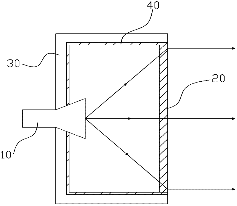
[0032] figure 2 It is a schematic diagram of the structure of the rear-fed radar antenna of the present invention. The antenna includes a feed source 10, a metamaterial panel 20, a housing 30, and a absorbing material layer 40. The feed source 10 is fixed on the housing 30 and the absorbing material layer 40 is tight. Sticking to the inner wall of the housing 30, the absorbing material layer 40 is connected to the metamaterial panel 20, and the absorbing material layer 40 and the metamaterial panel 20 together form a closed cavity, and the feed source 10 is located in the cavity.

[0033] Generally, the electromagnetic wave radiated from the feed source 10 is a spherical electromagnetic wave, but the far-field direction performance of the spherical electromagnetic wave is not good. It has...


PUM


Abstract

The invention relates to a feed-backward type radar antenna, which comprises a feed source and a metamaterial panel. The metamaterial panel comprises a plurality of core layers with same refractive index distributions. Each core layer comprises a plurality of metamaterial units. Each metamaterial unit comprises a unit substrate and an artificial micro-structure. According to the feed-backward type radar antenna disclosed by the invention, the far field power of the antenna is greatly increased by changing the refractive index distribution condition in the metamaterial panel; therefore, the propagation distance of the antenna is increased; simultaneously, because a wave absorption material layer is arranged in the cavity of the antenna, the front-to-back ratio of the antenna is increased, thus, the antenna has better directivity.

Description

technical field [0001] The invention relates to the field of radar antennas, more specifically, to a feed-back radar antenna using metamaterials. Background technique [0002] The feed-back antenna is also called the Cassegrain antenna, which consists of a parabolic main reflector 2, a hyperboloid secondary reflector 1, a feed horn 3 and a bracket 4, as shown in figure 1 shown. Since the real focus of the paraboloid main reflector 2 coincides with the virtual focus of the hyperboloid secondary reflector 1, and the phase center of the feed horn 3 coincides with the real focus of the hyperboloid secondary reflector 1, the electromagnetic wave emitted from the satellite passes through the paraboloid main The reflecting surface 2 is reflected once, and then reflected twice by the hyperboloid sub-reflecting surface 1, and then is focused on the phase center of the feed horn 3 and superimposed in the same phase. In this way, the radar antenna can receive or transmit electromagne...

Claims


Application Information

Patent Timeline
IPC IPC(8): H01Q15/00H01Q15/02H01Q19/06H01Q17/00
Inventor 刘若鹏季春霖岳玉涛殷俊
Owner KUANG CHI INST OF ADVANCED TECH
Why Eureka
Try Eureka