Fallback type radar antenna

A radar antenna and feed-type technology, applied in the field of radar antenna, to achieve the effect of increasing the front-to-back ratio, increasing the propagation distance, and enhancing the far-field power

Active Publication Date: 2013-04-10
KUANG CHI INST OF ADVANCED TECH +1
View PDF5 Cites 6 Cited by
  • Summary
  • Abstract
  • Description
  • Claims
  • Application Information

AI Technical Summary

Problems solved by technology

[0004] The purpose of the present invention is to overcome the difficulty of manufacturing parabolic reflectors and hyperboloid sub-reflectors in the prior art, and provide a radar antenna, which is no longer limited to the fixed formula of paraboloids, but is replaced by flat metamaterials, which saves space; and Improve the deflection problem of incident electromagnetic waves at large angles, and improve the efficiency of antenna energy radiation

Method used


Image

  • Fallback type radar antenna
  • Fallback type radar antenna
  • Fallback type radar antenna

Examples


Embodiment Construction

[0030] The present invention will be described in further detail below in conjunction with the embodiments and the accompanying drawings, but the embodiments of the present invention are not limited thereto.

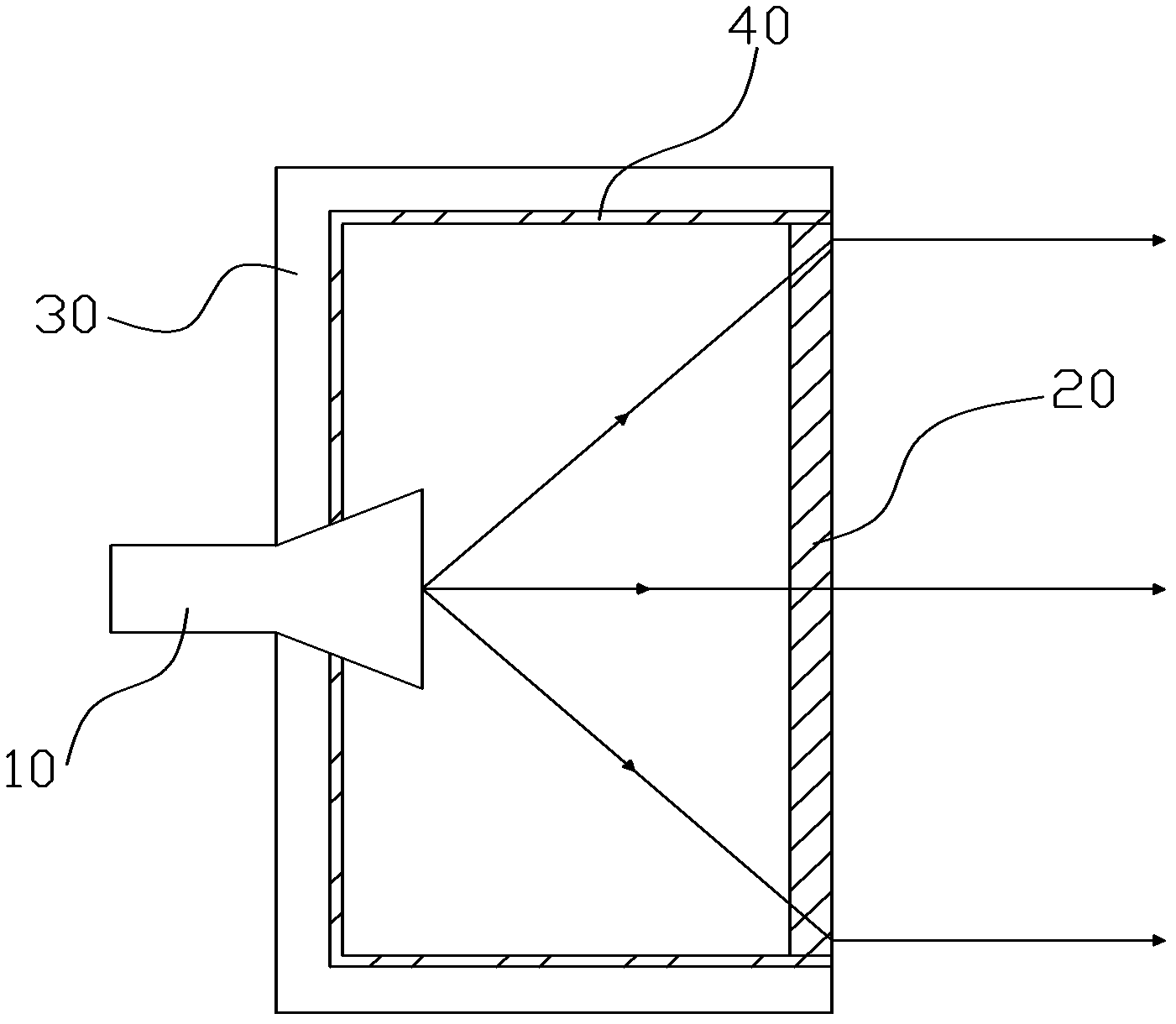
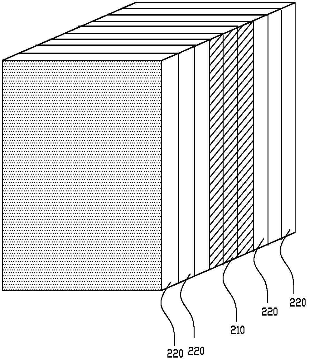
[0031] figure 2 It is a schematic diagram of the structure of the feed-back radar antenna of the present invention. The antenna includes a feed source 10, a metamaterial panel 20, a housing 30, and a wave-absorbing material layer 40. The feed source 10 is fixed on the housing 30, and the wave-absorbing material layer 40 is tight. Attached to the inner wall of the housing 30, the absorbing material layer 40 is connected to the metamaterial panel 20, and the absorbing material layer 40 and the metamaterial panel 20 together form a closed cavity, and the feed source 10 is located in the cavity.

[0032]Usually, the electromagnetic wave radiated from the feed source 10 is a spherical electromagnetic wave, but the far-field direction performance of the spherical electromagne...


PUM


Abstract

The invention relates to a fallback type radar antenna which comprises a feed source and a metamaterial panel. The metamaterial panel comprises a plurality of core layers with same refractive index distribution, each core layer of the metamaterial panel is composed of a plurality of metamaterial units, and each metamaterial unit comprises a unit substrate with one or a plurality of holes. The fallback type radar antenna greatly strengthens far-field power of the antenna and promotes a propagating distance of the antenna by changing a distribution condition of refractive indexes inside the metamaterial panel, and simultaneously an absorbing material layer is arranged inside a cavity of the antenna to increase a front-to-rear ratio of the antenna and enable the antenna to have directivity.

Description

technical field [0001] The invention relates to the field of radar antennas, and more specifically, to a feed-back radar antenna using metamaterials. Background technique [0002] The feed-back antenna is also called the Cassegrain antenna, which consists of a parabolic main reflector 2, a hyperboloid secondary reflector 1, a feed horn 3 and a bracket 4, as shown in figure 1 shown. Since the real focus of the paraboloid main reflector 2 coincides with the virtual focus of the hyperboloid secondary reflector 1, and the phase center of the feed horn 3 coincides with the real focus of the hyperboloid secondary reflector 1, the electromagnetic wave emitted from the satellite passes through the paraboloid main The reflecting surface 2 is reflected once, and then reflected twice by the hyperboloid sub-reflecting surface 1, and then is focused on the phase center of the feed horn 3 and superimposed in the same phase. In this way, the radar antenna can receive or transmit electrom...

Claims


Application Information

Patent Timeline
Patent Type & Authority Applications(China)
IPC IPC(8): H01Q15/00H01Q15/02H01Q19/06H01Q17/00
Inventor 刘若鹏季春霖岳玉涛李双双
Owner KUANG CHI INST OF ADVANCED TECH
Why Eureka
Try Eureka