Casing of electronic equipment

A technology of electronic equipment and casing, applied in the field of electronic equipment casing, can solve the problems of inconvenience, time-consuming and laborious operation, etc.

Inactive Publication Date: 2012-05-30
ZHEJIANG JIEYANG TECH CO LTD
View PDF2 Cites 2 Cited by
  • Summary
  • Abstract
  • Description
  • Claims
  • Application Information

AI Technical Summary

Problems solved by technology

However, this fixing method is time-consuming and laborious and extremely inconvenient to operate

Method used


Image

  • Casing of electronic equipment
  • Casing of electronic equipment
  • Casing of electronic equipment

Examples


Embodiment Construction

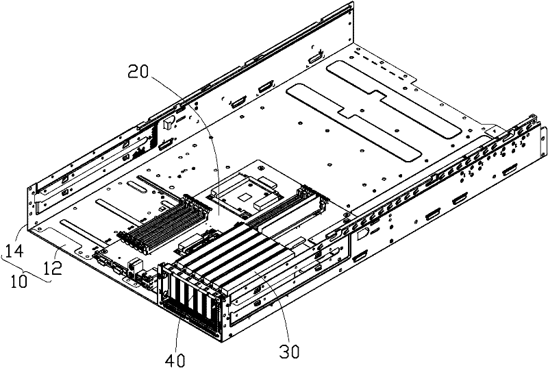
[0055] see figure 1 , The preferred embodiment of the electronic equipment case of the present invention includes a base 10 , a main board 20 , a plurality of expansion cards 30 and an expansion card fixing device 40 .

[0056] The base 10 includes a bottom plate 12 and two side plates vertically disposed on two long side edges of the bottom plate 12 . The main board 20 is fixed on the bottom board 12 . The electronic components in the housing of the electronic equipment, such as processor, memory, etc., are all fixed on the main board 20 and electrically connected with the main board 20 .

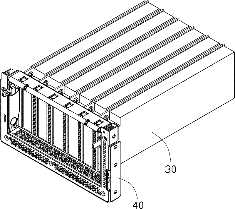
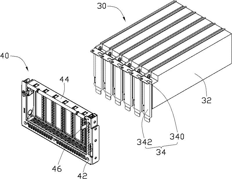
[0057] see figure 2 and image 3 , each expansion card 30 includes a main body 32 fixed on the main board 20 and electrically connected with the main board 20 and an I / O mask 34 . The I / O mask 34 is the same as the existing I / O mask, including a first positioning piece 340 in the horizontal direction and a second positioning piece 342 in the vertical direction.

[0058] Please also s...


PUM


Abstract

A casing of electronic equipment comprises a base, a main board and a plurality of expansion cards, wherein the main board is fixedly held in the base, and the expansion cards are mounted on the main board. Each expansion card comprises an I/O (input/output) matte, the I/O matte comprises a first positioning piece, the base is provided with a back window corresponding to the expansion cards, a fixing frame is pivotally mounted on the back window, the back window comprises a top plate, the fixing frame comprises a press portion which comprises a first fastener plate and a second a fastener plate opposite to the first fastener plate, the first positioning pieces and the top plate can be clamped between the first fastener plate and the second fastener plate so that the I/O mattes of the expansion cards can be fixed to the back window.

Description

technical field [0001] The invention relates to an electronic equipment casing. Background technique [0002] An electronic device, such as a server (Server) or a storage server (Storage Server), is usually equipped with a PCI (Peripheral Component Interconnect) standard or a PCI-E (Peripheral Component Interconnect Express) standard expansion card. The gold finger of the expansion card is plugged into the expansion card slot on the motherboard, and the rear window of the casing of the electronic equipment is provided with a fixing device to further fix the I / O mask on the expansion card. The I / O mask generally includes a first positioning piece and a second positioning piece perpendicular to the first positioning piece. In the prior art, the second positioning piece of the I / O mask is usually inserted into the limiting hole provided on the rear window, and then the first positioning piece of the I / O mask is fixed to the rear window by screws. However, this fixing method i...

Claims


Application Information

Patent Timeline
Patent Type & Authority Applications(China)
IPC IPC(8): H05K5/00H05K5/02
Inventor 陈炫璋张家铭陈炳宏
Owner ZHEJIANG JIEYANG TECH CO LTD
Why Eureka
Try Eureka