Single mirror optical scanner

A scanner and optical technology, applied in the direction of optics, optical components, instruments, etc., can solve the problems of low accuracy and range, achieve the effects of short total optical path, reduce optical loss, and reduce beam distortion

Active Publication Date: 2012-05-30
INTENZITY INNOVATION APS
View PDF1 Cites 5 Cited by
  • Summary
  • Abstract
  • Description
  • Claims
  • Application Information

AI Technical Summary

Problems solved by technology

The accuracy and range of angular deflection of such a scanner is still lower than that of a scanner with two mirrors

Method used


Image

  • Single mirror optical scanner
  • Single mirror optical scanner
  • Single mirror optical scanner

Examples


Embodiment Construction

[0051] The present disclosure will be described more fully hereinafter with reference to the accompanying drawings, in which exemplary embodiments of the disclosure are shown. The drawings are schematic and simplified for clarity and only show details necessary for understanding the disclosure, while other details are omitted. In the drawings, the same reference numerals are used for the same or corresponding parts.

[0052] The present disclosure may be embodied in different forms in addition to the embodiments shown and should not be construed as limited to the embodiments set forth herein.

[0053] In the following description, specific details are set forth in order to provide a thorough understanding of the various disclosed embodiments. However, one skilled in the art will appreciate that the embodiments may be practiced without one or more of these specific details, or with other methods, components, materials, and the like. In other instances, well-known structures o...


PUM


Abstract

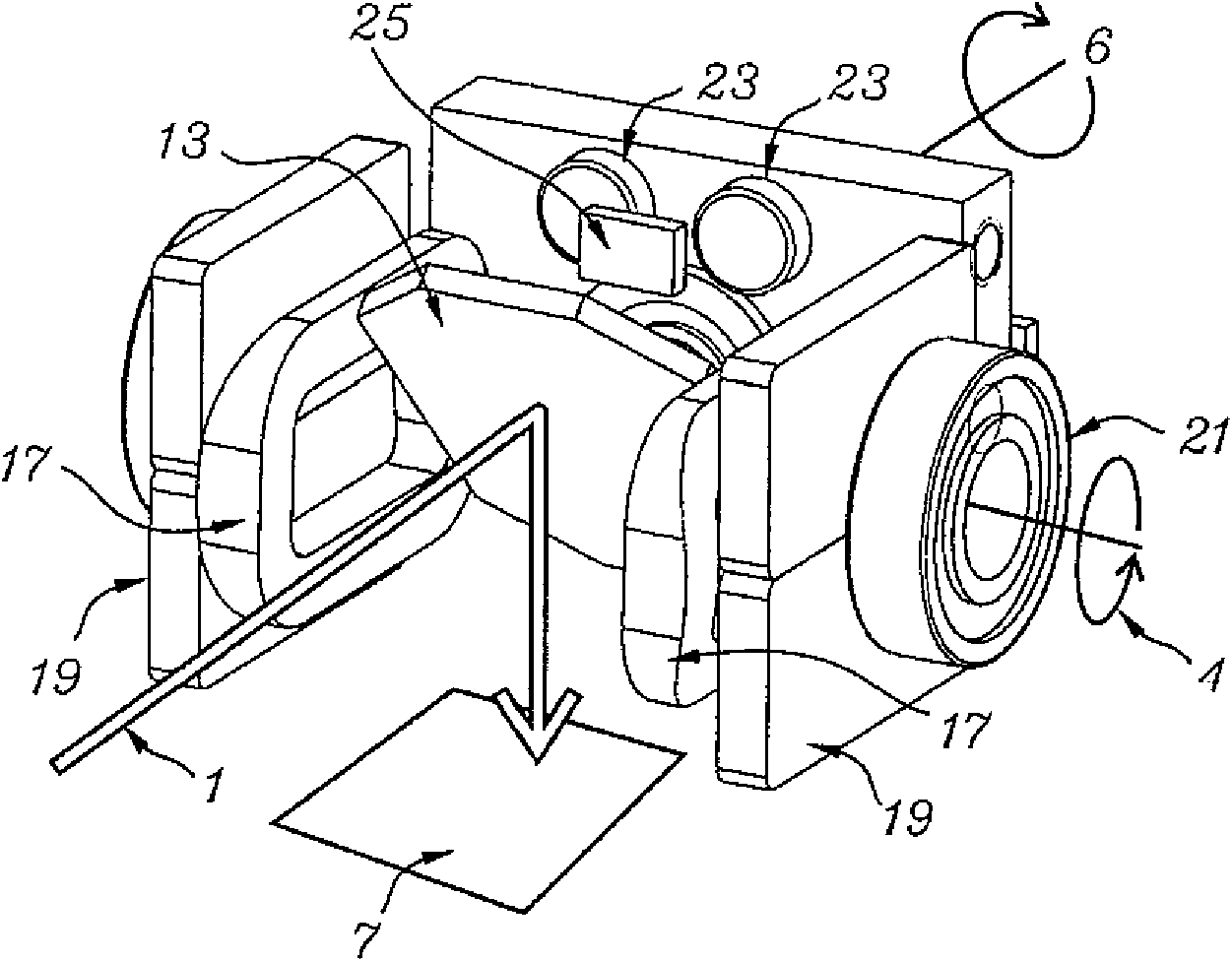
The present disclosure is directed to a device having an optical scanner, the optical scanner structured to include a mirror, a first actuator that rotates the mirror around a first axis of rotation, a first angular position sensor that senses an angular position of the mirror around the first axis of rotation, a second actuator that rotates the mirror around a second axis of rotation, a second angular position sensor that senses the angular position of the mirror around the second axis of rotation, and a controller coupled to the first and second drivers and structured to drive the respective first and second actuators to rotate the mirror into respective specific angles around the axes of rotation as sensed by the respective first and second angular position sensors.

Description

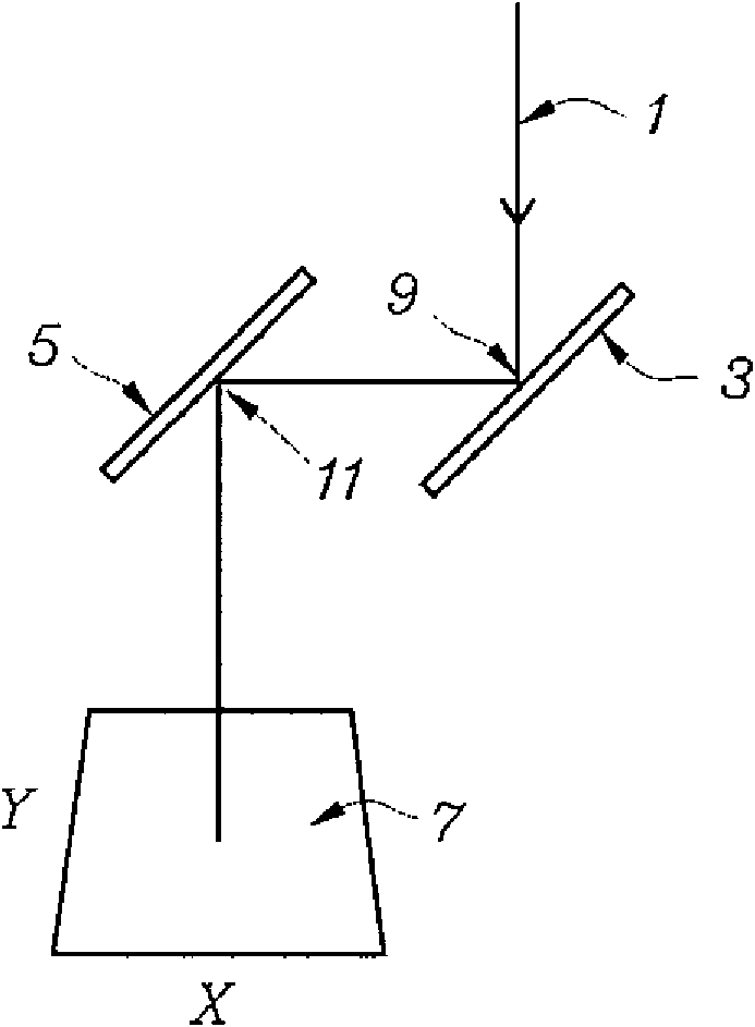
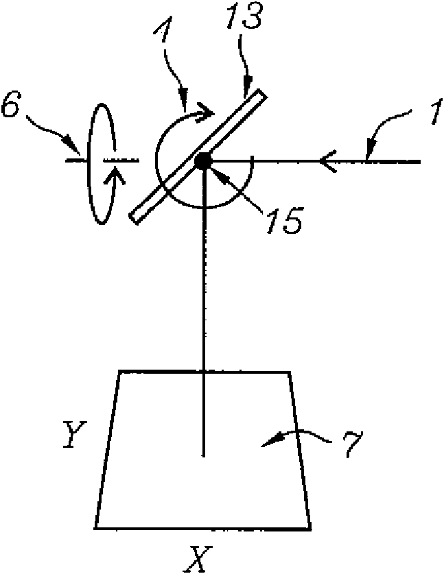
technical field [0001] The present disclosure relates to a compact optical scanner with a single moving mirror arranged to deflect an electromagnetic beam to a desired direction in space with high precision given by spherical coordinates (azimuth, inclination). Background technique [0002] In general, known scanners for scanning a beam of light on a two-dimensional surface comprise two mirrors mounted to rotate about mutually perpendicular axes of rotation so that one mirror scans the beam along the x-axis on the surface and the other along Scan the beam along the y-axis on the surface. [0003] Scanners with a single moving mirror are also known, where the mirror is arranged to rotate about two axes of rotation. The accuracy and range of angular deflection of such scanners is still lower than that of scanners with two mirrors. Contents of the invention [0004] According to one embodiment of the present disclosure, the optical scanner is provided with mirrors mounted t...

Claims


Application Information

Patent Timeline
Patent Type & Authority Applications(China)
IPC IPC(8): G02B26/10
CPCG02B26/101G02B7/1821
Inventor 卡斯伯·多勒瑞斯比亚尔尼·阿萨
Owner INTENZITY INNOVATION APS
Why Eureka
Try Eureka