
Method for sticking massively produced simple lenses and metal brackets

A metal bracket and simple lens technology, applied in installation, optics, instruments, etc., can solve the problems of dislocation of the metal bracket and the simple lens, adhesive glue flowing to the lens, low operation efficiency, etc., achieving simple structure, easy operation, The effect of high pass rate

Inactive Publication Date: 2011-06-15
大连艾科科技开发有限公司
View PDF4 Cites 2 Cited by
  • Summary
  • Abstract
  • Description
  • Claims
  • Application Information

AI Technical Summary

Problems solved by technology

The existing positioning fixture is processed with a placement hole on the table body, and the bonded metal bracket and simple lens are placed in the hole. Since there is no vertical surface and support surface for the card position inside the hole, it is easy to appear in the oven. The misalignment of the metal bracket and the simple lens causes inaccurate positioning between the two, and often a small amount of adhesive glue flows onto the lens, causing lens contamination. Not only is the pass rate low, but the work efficiency is also low.

Method used


Image

  • Method for sticking massively produced simple lenses and metal brackets
  • Method for sticking massively produced simple lenses and metal brackets
  • Method for sticking massively produced simple lenses and metal brackets

Examples


Embodiment Construction

[0016] Method steps of the present invention are as follows:

[0017] a. Place the metal bracket in the through hole of the positioning jig, and apply glue evenly on the upper surface.

[0018] B. Then place the lens in the slot of the positioning jig. At this time, the metal bracket is on the bottom and the lens is on the top for complete positioning.

[0019] c. Baking;

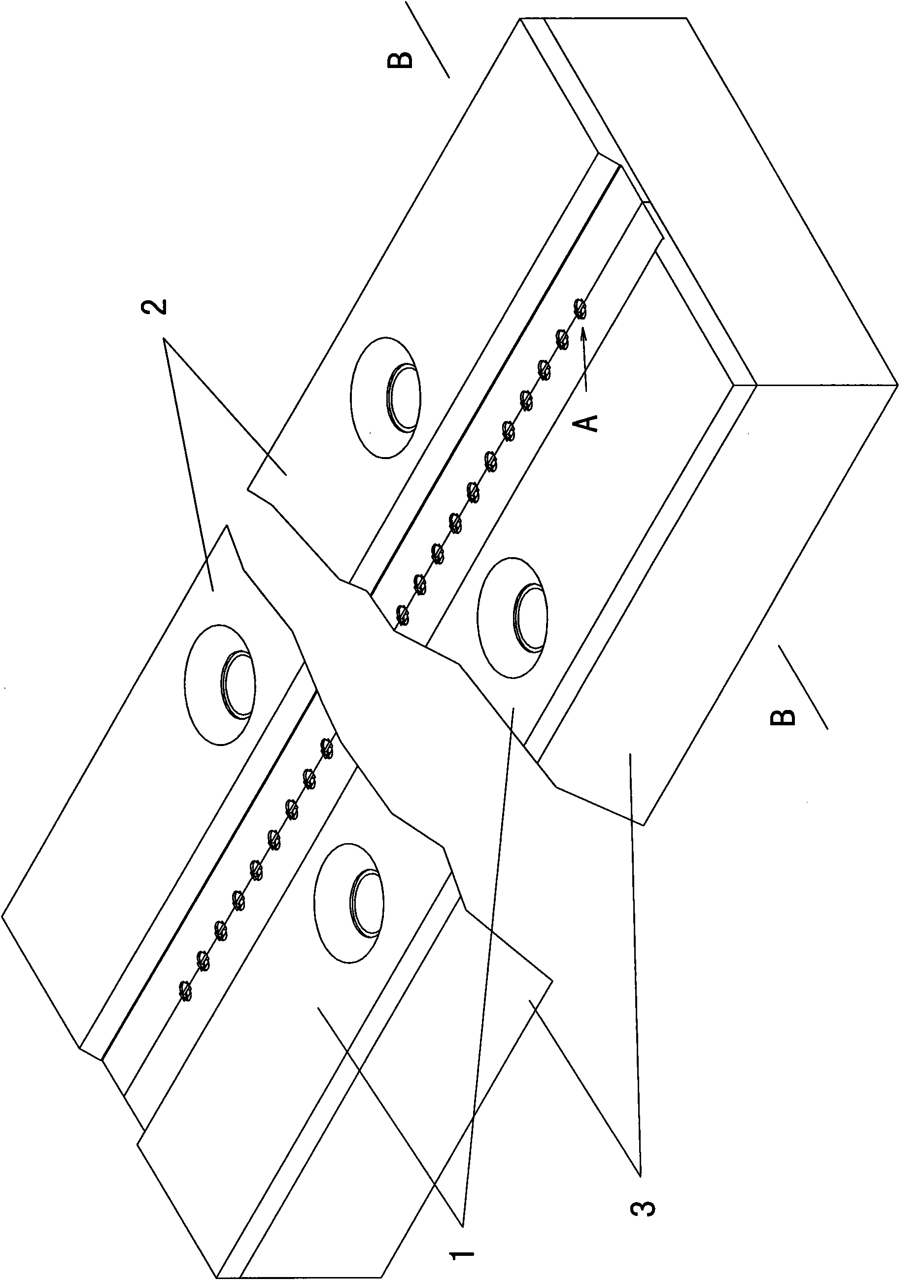
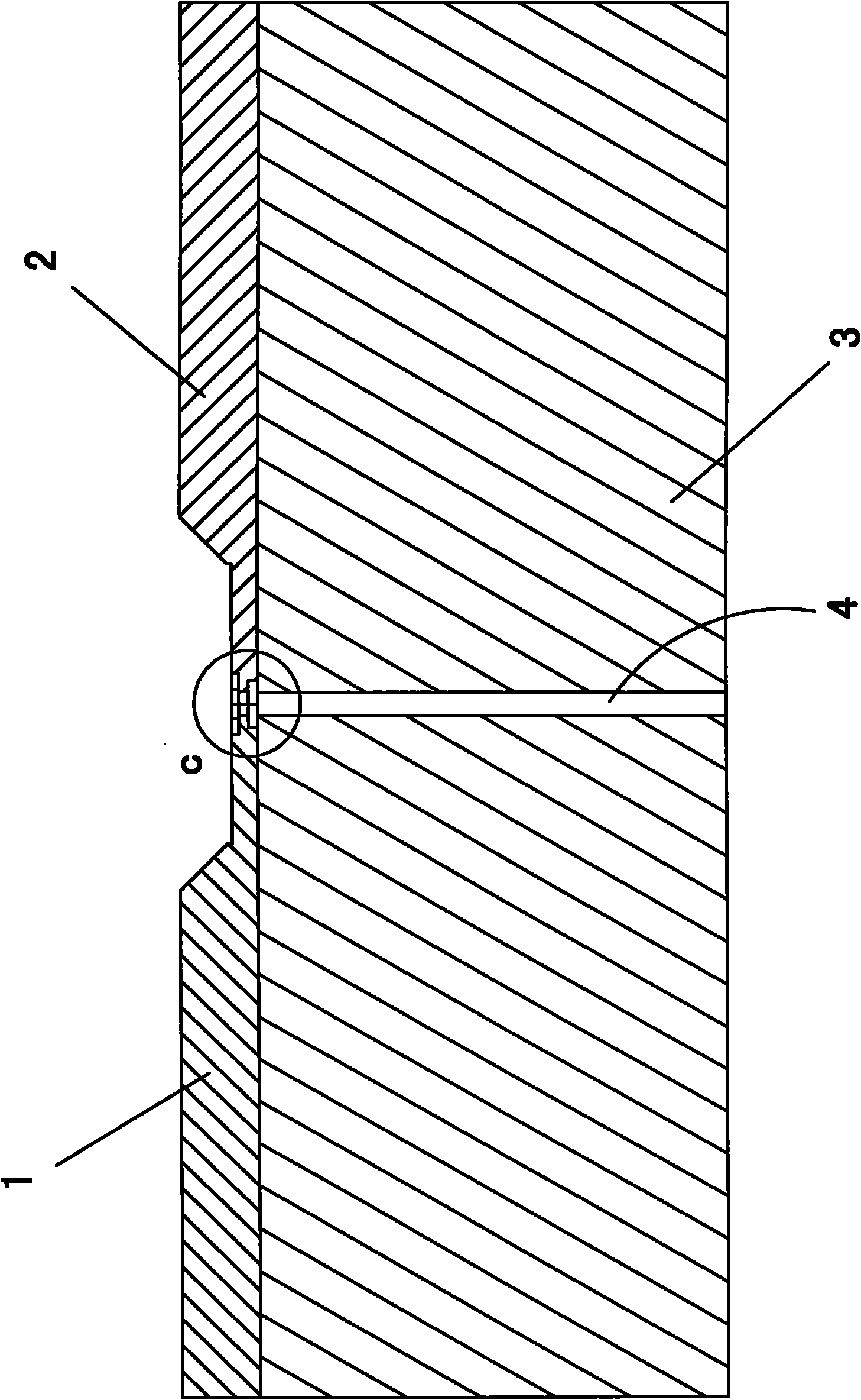
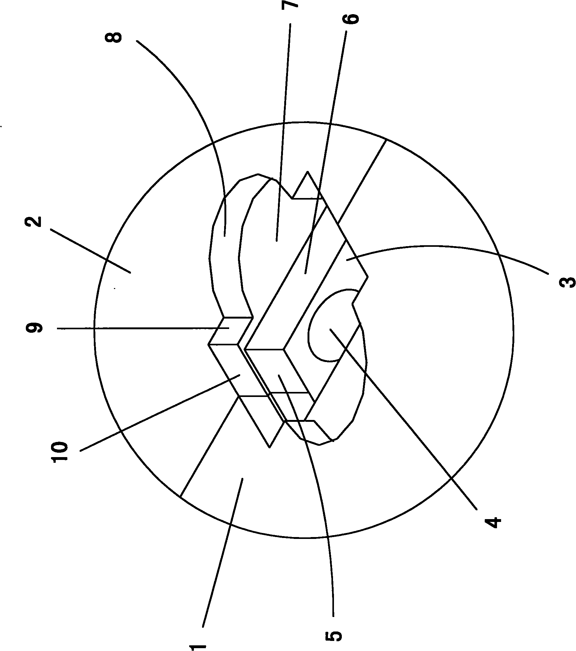
[0020] The concrete structure of above-mentioned positioning jig is: as figure 1 , 2 , 3, and 4 show: there is a cuboid base plate 3, and a plurality of through holes 4 arranged in a straight line are processed on the longitudinal center line of the base plate 3.

[0021] There are symmetrically arranged left upper plate 1 and right upper plate 2 on the bottom plate 3, and the thickness dimension of the left upper plate 1 and right upper plate 2 close to each other is smaller than the outer thickness dimension.

[0022] There is a slot A for placing a simple lens at the joint surface where the upper lef...


PUM


Abstract

The invention discloses a method for sticking massively produced simple lenses and metal brackets, which comprises the following steps of: a. placing the metal bracket into a through hole in a positioning jig, and coating glue on the upper surface uniformly; b. placing the lens in a slot of the positioning jig, wherein the metal bracket is at the lower side, and the lens is completely positioned on the upside; and c, baking. The structure of the positioning jig comprises a bottom plate, wherein a plurality of through holes arranged linearly are formed on the bottom plate, a left upper plate and a right upper plate are symmetrically arranged on the bottom plate, a slot for accommodating the simple lens is formed at the contact joint face of the left upper plate and the right upper plate and positioned above each through hole, a lens support face is formed in the slot, symmetrical and vertical arc faces are arranged on the two sides of the slot, and the two ends of the slot have symmetric and vertical upper end faces and upper sides vertical to the upper end faces. The method has the advantages that: the structure is simple; the operation is easy; the efficiency is high; the positioning is accurate; the lens is not polluted; and the qualified rate is high.

Description

technical field [0001] The invention relates to a simple lens and metal bracket bonding method suitable for mass production. Background technique [0002] At present, the method of bonding the simple lens and the metal bracket is to use adhesive glue to bond the end of the metal bracket with one side of the simple lens, and then place the bonded metal bracket and simple lens on the positioning fixture. Then put the metal bracket, simple lens and positioning fixture into the oven to bake for a certain period of time to make it firm. The existing positioning fixture is processed with a placement hole on the table body, and the bonded metal bracket and simple lens are placed in the hole. Since there is no vertical surface and support surface for the card position inside the hole, it is easy to appear in the oven. The misalignment between the metal bracket and the simple lens leads to inaccurate positioning between the two, and often a small amount of adhesive glue flows onto t...

Claims


Application Information

Patent Timeline
IPC IPC(8): G02B7/02
Inventor 贾秀玲刘学洋
Owner 大连艾科科技开发有限公司
Learn More