Device and method for realizing spatial three-dimensional variable curvature bending of pipe

A technology of variable curvature and pipe material, which is applied in the field of devices that realize three-dimensional variable curvature bending of pipe materials, can solve the problems of complex structure, high manufacturing cost, and bending defects of the bending device, and achieve simple structure, low manufacturing cost, and reduced wrinkling Effect

Inactive Publication Date: 2012-06-13
SHANGHAI SECOND POLYTECHNIC UNIVERSITY
View PDF8 Cites 22 Cited by
  • Summary
  • Abstract
  • Description
  • Claims
  • Application Information

AI Technical Summary

Problems solved by technology

However, the limitations of the bending process are: the radius of the bending die required to bend parts with a large curvature radius is too large, so the radius of curvature of the parts is required to be less than 500mm; the structure of the bending device with three different bending radii is extremely complicated and the manufacturing cost is expensive; the bending process The friction between the tube blank and the mold belongs to sliding friction, which is prone to bending defects, such as wrinkling, cracking and other problems

Method used


Image

  • Device and method for realizing spatial three-dimensional variable curvature bending of pipe
  • Device and method for realizing spatial three-dimensional variable curvature bending of pipe
  • Device and method for realizing spatial three-dimensional variable curvature bending of pipe

Examples


Embodiment 1

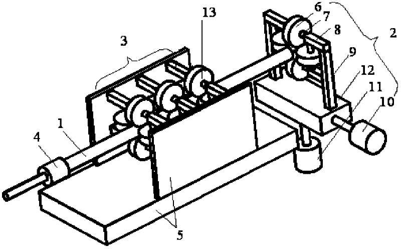
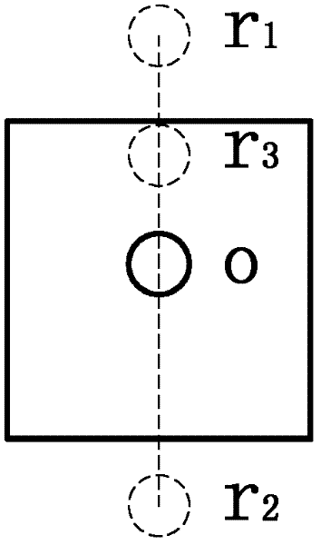
[0040] Prepare multiple curved tubes with constant radius and straight segments alternating in the plane, such as figure 2 , Figure 5 As shown, the specific method is as follows: the pipe 1 enters the bending unit 2 through the guide unit 3 under the action of the rear push rod 4, and stops moving forward when the pipe 1 is fed to the first position that needs to be bent, and then uses the vertical motor 11 Drive the tube center on bending unit 2 according to figure 2 The trajectory moves from point o to r 1 Stop after the point, and now the rear push rod 4 promotes the pipe material 1 to move forward. When the end point of the first bending radius reaches the front end of the guide unit 3, the center of the pipe on the bending unit 2 is driven by the vertical motor 11 from r 1 The point returns to point o, and the pipe 1 moves forward all the time during this process, thus completing the first bending with a fixed radius. After the center of the pipe material on the be...

Embodiment 2

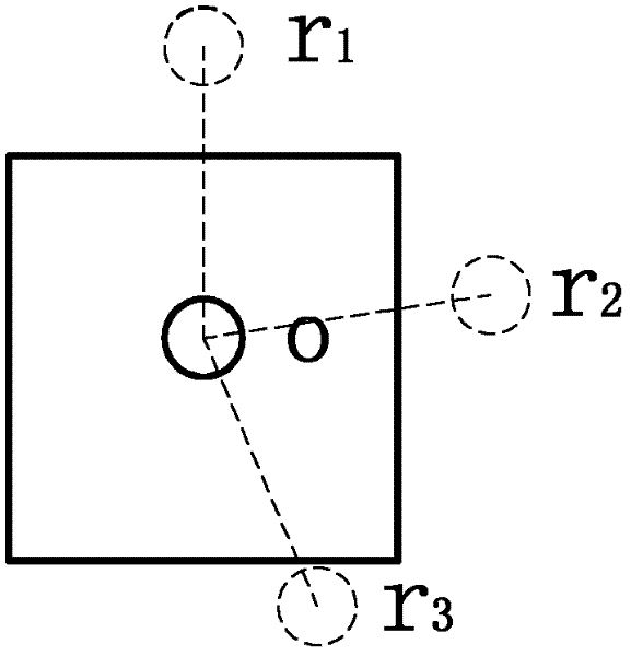
[0042] Prepare multiple curved pipes with constant radius and straight segments in space, such as image 3 , Image 6 As shown, the specific method is as follows: the pipe 1 enters the bending unit 2 through the guide unit 3 under the action of the rear push rod 4, and stops moving forward when the pipe 1 is fed to the first position that needs to be bent, and then is driven by a motor 11 Tube center on bending unit 2 according to image 3 The trajectory moves from point o to r 1 Point stops, and this moment, rear push rod 4 promotes pipe material 1 to move forward again. When the end point of the first bending radius reaches the front end of the guide unit 3, the center of the pipe on the bending unit 2 is driven by the vertical motor 11 from r 1 The point returns to point o, and the pipe 1 moves forward all the time during this process, thus completing the first bending with a fixed radius. After the center of the pipe on the bending unit 2 returns to point o, it stays f...

Embodiment 3

[0044] Prepare multiple curved tubes with varying radius and straight segments in the plane, such as figure 2 , Figure 7 As shown, the specific method is as follows: the pipe material 1 enters the bending unit 2 through the guide unit 3 under the action of the rear push rod 4, and when the pipe material 1 is fed to the first position that needs to be bent, the center of the pipe material on the bending unit 2 starts to be vertical Driven by the motor 11 according to figure 2 The trajectory moves from point o to r 1 point, the pipe 1 is always moving forward in this process. When the end point of the first bending radius reaches the front end of the guide unit 3, the center of the pipe on the bending unit 2 is driven by the vertical motor 11 from r 1 Point returns to point o, and pipe material 1 moves forward all the time during this process, thus completing the first bending with variable radius. The bending unit 2 stays for a while after returning to the o point, and t...


PUM


Abstract

The invention provides a device for realizing spatial three-dimensional variable curvature bending of a pipe. The device comprises a pipe, roller groups, a bending unit, a guiding unit, a rear push rod and a fixed rack, wherein each roller is connected with a connecting rod by a bearing; the four rollers surround the circumference direction of the pipe; the axes of the rollers are vertical pairwise and are arranged in a cross manner; the two connecting rods connected with a pair of rollers with longitudinal axes are fixed on two parallel beams respectively; the two connecting rods connected with a pair of rollers with transverse axes are parallel to each other and are vertically fixed on the beams respectively; the guiding unit comprises at least three roller groups; the two beams of each roller group are vertically fixed on two side wall plates of the fixed rack; two columns of the bending unit are vertically fixed on a baseplate respectively; the two beams of the roller groups are vertically fixed with the two columns; a vertical motor 11 is connected at the bottom of the baseplate; and a horizontal motor 10 is connected at one end of the baseplate. The device has simple structure, low cost and low energy consumption, can prepare various spatial variable curvature bending pipes and effectively reduce the defects such as wrinkling and fracture.

Description

technical field [0001] The invention relates to a device and method for realizing three-dimensional variable curvature bending of pipe material space. Background technique [0002] Bending pipe fittings are increasingly used in household appliances, automobiles, aerospace and other fields, and the industry has higher and higher requirements for the quality of bent pipes. For this reason, a variety of methods and corresponding devices for improving the bending performance of pipes have been proposed at home and abroad. At present, the most widely used methods are rolling bending and winding bending. It is the roller group that determines the bending performance of the roll bending process. The early roller group consisted of 2 rollers, and later developed to 3 or 4 rollers. When forming large-sized pipe fittings, this process needs to arrange the support mechanism, guide mechanism, and hydraulic cylinder. The position and other parts are adjusted accordingly (patent number: ...

Claims


Application Information

Patent Timeline
Patent Type & Authority Applications(China)
IPC IPC(8): B21D7/08
Inventor 苑文婧田浩彬刘晓航
Owner SHANGHAI SECOND POLYTECHNIC UNIVERSITY
Why Eureka
Try Eureka