
Method for machining bottom R of reverse taper end milling cutter

A processing method and end mill technology, which is applied in the processing field of reverse taper end mill midsole R, can solve problems such as hidden dangers in the finishing process, changes in the internal organization of the tool, and failure to meet production needs.

Inactive Publication Date: 2012-06-20
SHENYANG AIRCRAFT CORP
View PDF3 Cites 4 Cited by
  • Summary
  • Abstract
  • Description
  • Claims
  • Application Information

AI Technical Summary

Problems solved by technology

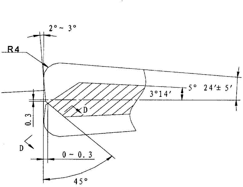
[0002] The reverse taper end mill with bottom R is a tool widely used in equipment manufacturing industries such as machinery, aviation and automobiles, such as figure 1 As shown, the structural feature of the reverse taper milling cutter product with bottom R is that the head of the single taper milling cutter has a tangential transition between the R value and the reverse taper. Usually, the R fillet is initially processed, and in the finishing process There will be an annealing effect in the process, which reduces the hardness of the tool, changes the internal structure of the tool, reduces the quality of the tool, and cannot meet the production requirements; another form of processing is that it is possible to quantitatively reserve the back taper during the turning process of the rough machining process. The size value of the big end of the end mill brings a lot of troubles and hidden dangers to the quality of the finishing process, the efficiency is greatly reduced, and the quality of the product cannot be guaranteed

Method used


Image

  • Method for machining bottom R of reverse taper end milling cutter
  • Method for machining bottom R of reverse taper end milling cutter
  • Method for machining bottom R of reverse taper end milling cutter

Examples


Embodiment Construction

[0017] Such as figure 1 As shown, a method for processing the bottom R of a reverse taper end mill, wherein R=4mm, is characterized in that it comprises the following steps:

[0018] 1) Raw material preparation: According to the drawing requirements of the reverse taper end mill, there is a margin for the width and length of the milling cutter. Its overall shape is a cylinder at the front end and a cone at the back end;

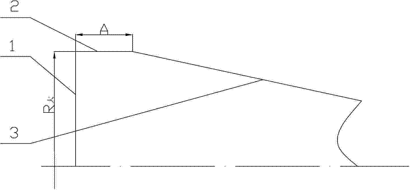
[0019] 2) if figure 2 As shown, roughing:

[0020] 2.1) Clamp with the top, turn the front end face, and see the light, so that the end face becomes the reference plane;

[0021] 2.2) Use the grinding method to grind the cylinder at the front end so that the outer circle is directly the diameter R of the large end 大 ;

[0022] 2.3) Grinding the tapered surface at the rear end until the length of the cylinder is A, where A=the value of the radius of the bottom R, that is, A=4mm;

[0023] 3) Cut the forming grinding wheel with a template of the size of th...


PUM


Abstract

The invention relates to a method for machining a bottom R of a reverse taper milling cutter. The method comprises the following steps of: 1) preparing a raw blank, namely leaving allowance in the directions of width and length of the milling cutter according to the requirement of a drawing of the reverse taper milling cutter, wherein in the integral appearance of the milling cutter, the front end is a cylinder and the rear end is a cone; 2) performing rough machining, namely 2.1) clamping by using a tip, and turning a front end face until light can be seen, so that the end face is used as a reference plane; 2.2) grinding the cylinder at the front end in a grinding mode, so that the diameter of an excircle is used as the diameter Rlarge of a large end; and 2.3) grinding a taper surface at the rear end in a grinding mode until the length of the cylinder is A; 3) cutting a formed grinding wheel by using a sample plate with the size which is the same as the bottom R; and 4) performing finish machining, namely allowing the formed grinding wheel to lean against two end corners of the reverse taper end milling cutter to ensure that a tangent point of a fillet coincides with an intersection point of the taper surface, so that the size requirement of the drawing can be ensured. By the method, the detection time and machining time are reduced greatly, and the production efficiency and quality of the machined products are improved.

Description

technical field [0001] The invention relates to a processing method for the midsole R of a reverse taper end mill, which is used for processing the midsole R of the reverse taper end mill. Background technique [0002] The reverse taper end mill with bottom R is a tool widely used in equipment manufacturing industries such as machinery, aviation and automobiles, such as figure 1 As shown, the structural feature of the reverse taper milling cutter product with bottom R is that the head of the single taper milling cutter has a tangential transition between the R value and the reverse taper. Usually, the R fillet is initially processed, and in the finishing process There will be an annealing effect in the process, which reduces the hardness of the tool, changes the internal structure of the tool, reduces the quality of the tool, and cannot meet the production requirements; another form of processing is that it is possible to quantitatively reserve the back taper during the turn...

Claims


Application Information

Patent Timeline
IPC IPC(8): B23P15/34
Inventor 邓楠
Owner SHENYANG AIRCRAFT CORP
Learn More