Ball head pin locking device

A technology of locking device and ball stud, which is applied in the direction of pivot connection, etc., can solve the problems of complex structure, poor stress condition, easy loosening, etc., and achieve the effect of large contact area

Inactive Publication Date: 2012-06-20
CHINA NORTH VEHICLE RES INST
View PDF3 Cites 5 Cited by
  • Summary
  • Abstract
  • Description
  • Claims
  • Application Information

AI Technical Summary

Problems solved by technology

This type of connection is either costly or easy to loosen. Not only is the force situation bad, but the locking screw needs to bear all the force, it will also cause complex structure and difficult adjustment.

Method used


Image

  • Ball head pin locking device
  • Ball head pin locking device
  • Ball head pin locking device

Examples


Embodiment Construction

[0040] The ball stud locking device of the present invention will be further described in detail below in conjunction with the accompanying drawings.

[0041] 1. Basic composition

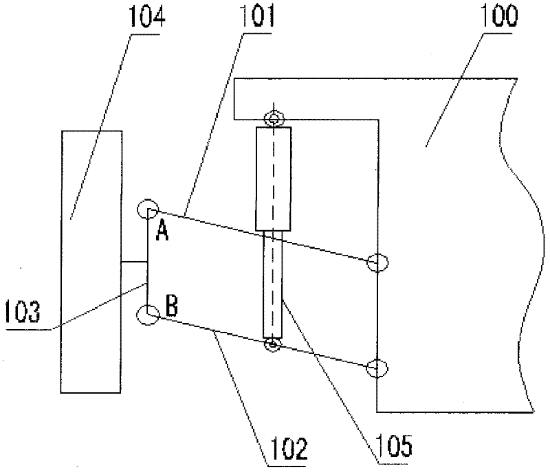
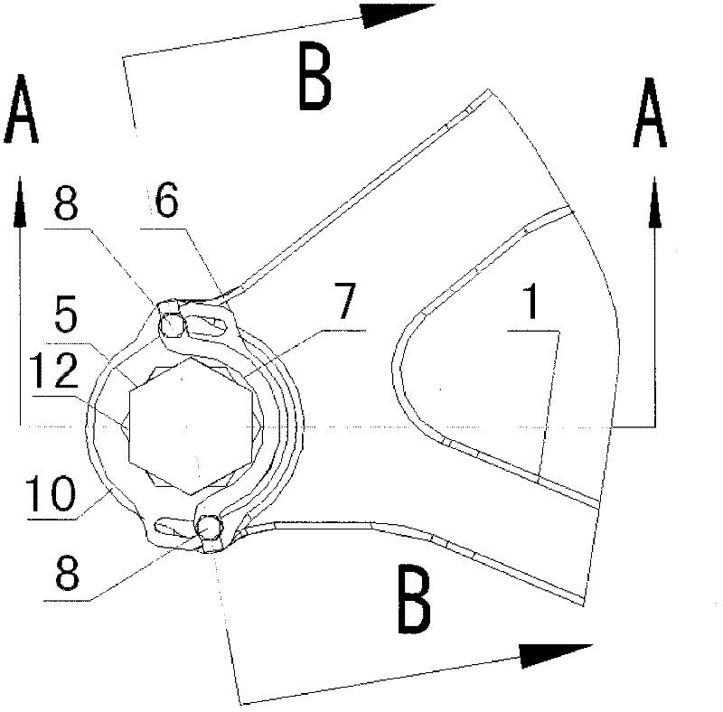
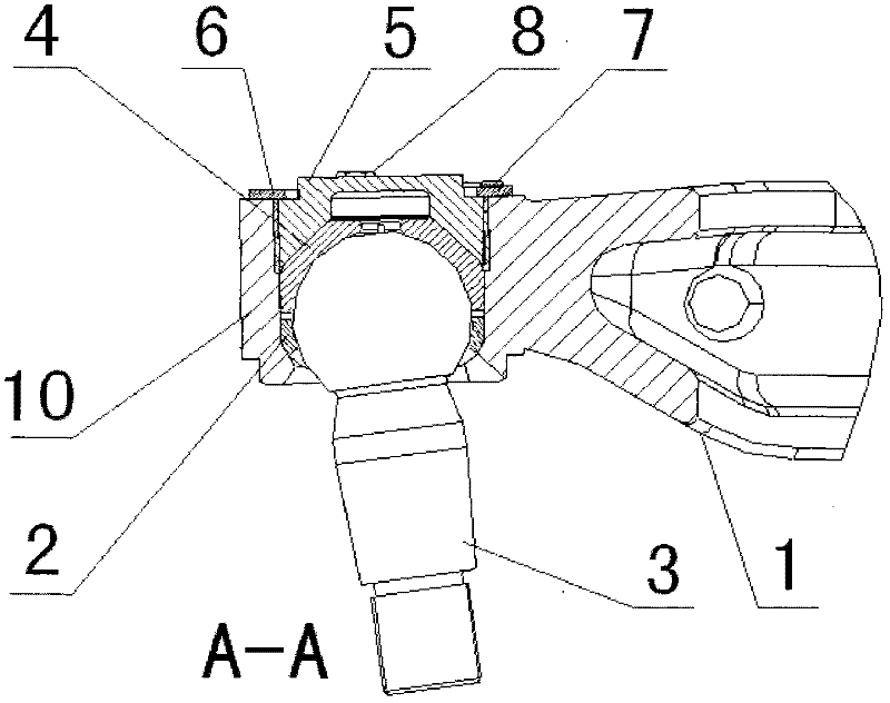
[0042] Such as Figure 2-Figure 4 As shown, the ball stud locking device of the present invention includes being installed on the cross arm 1 (this cross arm can be figure 1 The ball seat 10, the lower ball bowl 2, the ball stud pin 3, the upper ball bowl 4, the ball bowl gland 5, the locking gasket 6, Arch washer 7 and locking screw 8.

[0043] The upper ball bowl 4 and the lower ball bowl 2 are all placed in the ball head seat 10. After the upper and lower ball bowls are fastened together, the ball head of the ball stud pin 3 is clamped. The radial direction of the ball head is close to the ball head seat 10. Constraint; the lower outer spherical surface of the ball head is supported by the tapered surface at the bottom of the inner surface of the ball head seat, forming a constraint on the lo...


PUM


Abstract

The invention provides a ball head pin locking device, which comprises a ball head seat, a lower ball bowl, a ball head pin, an upper ball bowl, a ball bowl pressing cover, a locking gasket, a bow-shaped gasket and a locking bolt. The upper ball bowl and the lower ball bowl are arranged in the ball head seat. The upper ball bowl and the lower ball bowl are locked to clamp the ball head part of the ball head pin. The ball bowl pressing cover forms a pressing connection on the upper ball bowl. The periphery surface of the ball bowl pressing cover is provided with outer threads, and form a thread connection with a thread hole arranged in the ball head seat. The upper surface of the ball bowl pressing cover is provided with a boss, wherein the boss is inserted into the inner opening of the locking gasket, and sequentially penetrates through the bow-shaped gasket and the locking gasket through the locking bolt to fix the bow-shaped gasket and the locking gasket on the top surface of the ball head seat. According to the present invention, the ball head pin locking device has advantages of high reliability, good locking effect, convenient use and regulation, and the like; when the locking amount is adjusted, the adjustment of any rotation angles of the ball bowl pressing cover can be achieved without unscrewing of the locking bolt so as to conveniently adjust the locking amount.

Description

technical field [0001] The invention belongs to the technical field of ball studs, in particular, the invention relates to a locking device for fixing ball studs of vehicle suspension. Background technique [0002] Most of the upper and lower wishbones of the current vehicle double wishbone suspension are connected to the wheel hub by ball studs. The ground force transmitted by the ball stud is transmitted to the swing arm through the ball gland. figure 1 The schematic diagram of the double wishbone suspension mechanism is shown, such as figure 1 As shown, the suspension generally consists of an upper cross arm 101, a lower cross arm 102, a wheel 104, and an oil-pneumatic spring 105. It forms a four-bar mechanism together with the wheel hub assembly 103 and the vehicle body 100 to provide guidance for the wheels 104 and to The vehicle body 100 provides support. Typically ball studs are used for figure 1 A and B in the two places are connected. [0003] For double wishbo...

Claims


Application Information

Patent Timeline
Patent Type & Authority Applications(China)
IPC IPC(8): F16C11/06
Inventor 刘广征施睿王东亮郭晓燕
Owner CHINA NORTH VEHICLE RES INST
Why Eureka
Try Eureka