
Novel bar code scanner

A new type of barcode scanning technology, applied in electromagnetic radiation induction and other directions, can solve problems such as difficult correction and complex structure, and achieve the effect of reducing the scanning error rate, improving the scanning speed, and reducing the labor intensity of scanning.

Inactive Publication Date: 2014-08-27
HUBEI CHINA TOBACCO IND
View PDF4 Cites 0 Cited by
  • Summary
  • Abstract
  • Description
  • Claims
  • Application Information

AI Technical Summary

Problems solved by technology

But its structure is complicated, and it is difficult to correct once it goes wrong

Method used


Image

  • Novel bar code scanner
  • Novel bar code scanner
  • Novel bar code scanner

Examples


Embodiment Construction

[0014] The technical solution of the present invention will be further described in detail below in conjunction with the accompanying drawings.

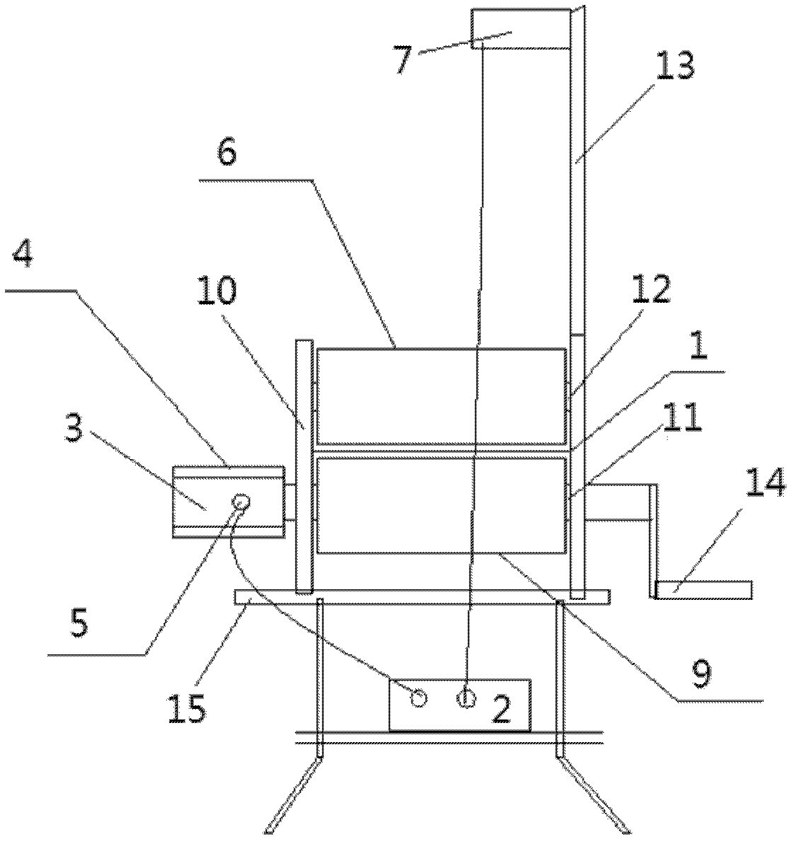
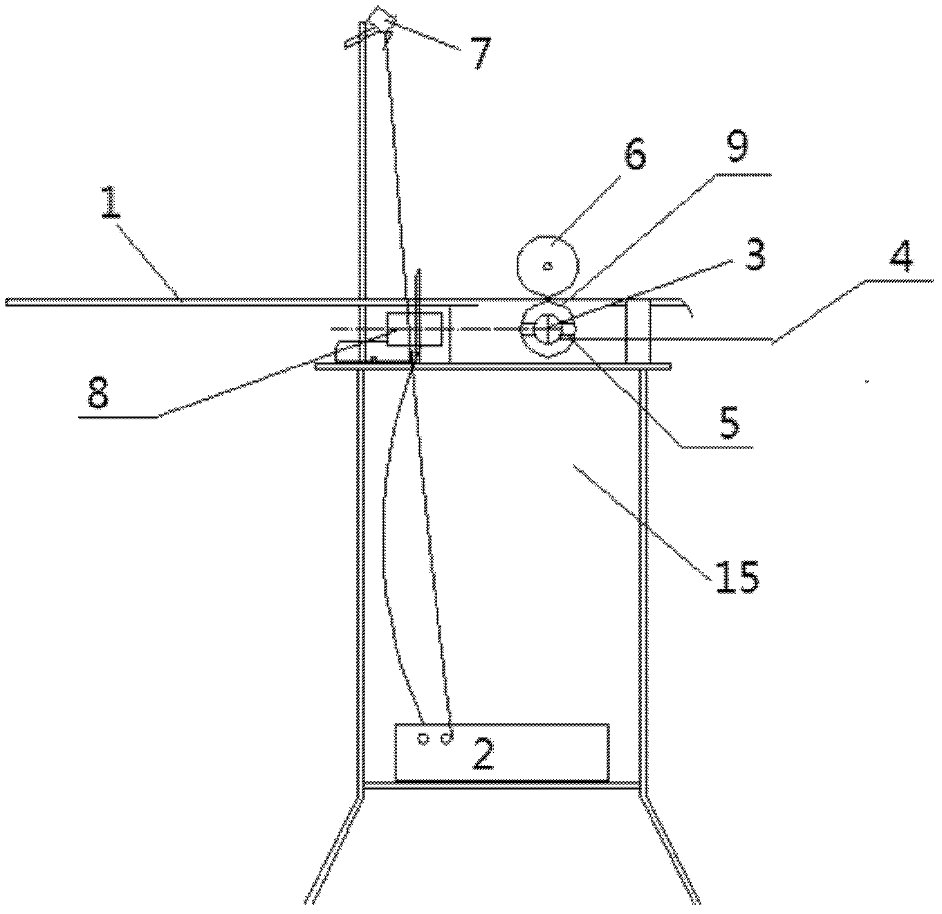
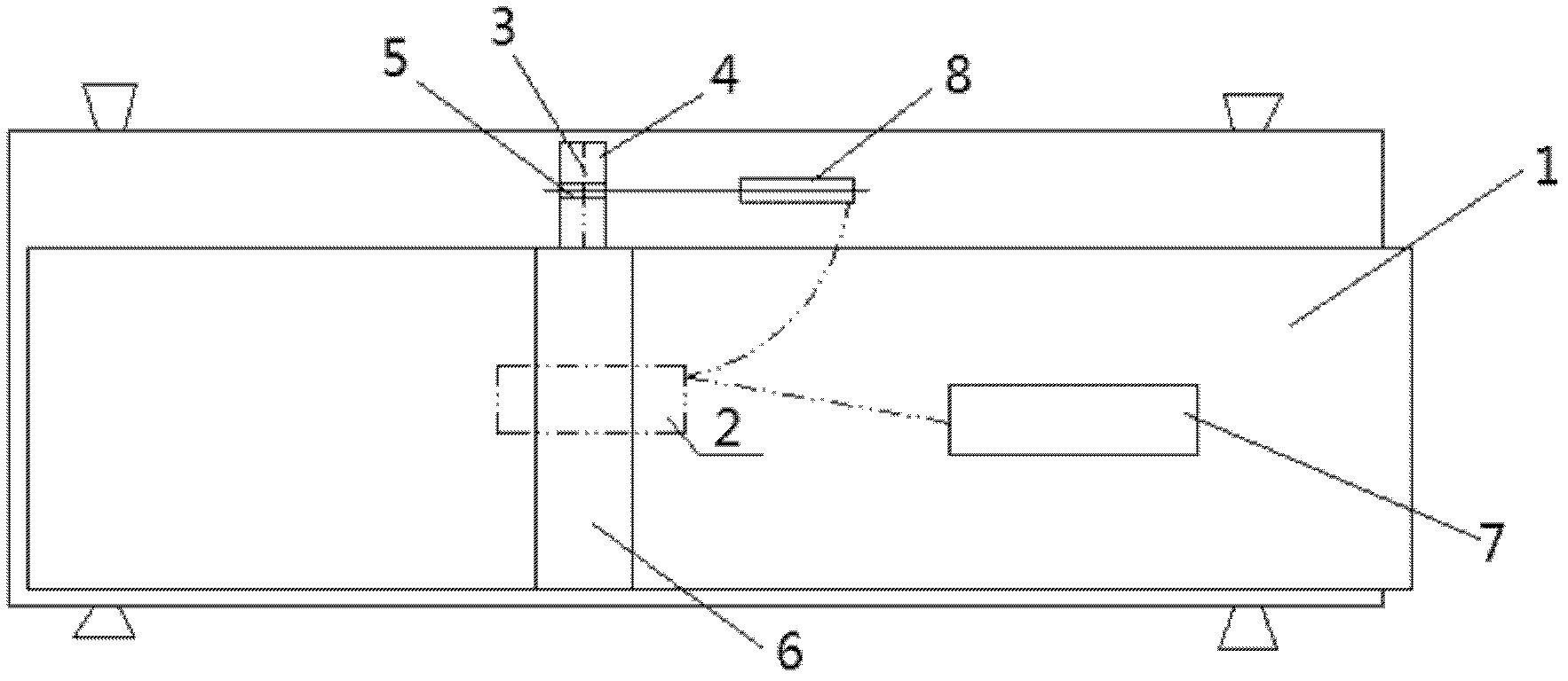
[0015] Such as figure 1 , figure 2 As shown, the present invention comprises a transmission bracket 10, a drive roller 9 is fixed on the transmission bracket 10, a pinch roller 6 is fixed above the drive roller 9, a transmission shaft 11 of the drive roller 9 and a rotating shaft 12 of the pinch roller pass through a gear or a belt Connect, drive belt 1 is housed between drive roller 9 and pressure roller 6, and one end of drive shaft 11 of described drive roller is connected with cylinder 4. Such as Figure 4 As shown, there is a through hole 5 on the cylinder 4, and a reflective baffle 3 is fixed inside the cylinder 4, and the surface plane of the reflective baffle 3 is perpendicular to the line connecting the centers of the two circular holes 5, and on one side of the cylinder 4 and The position corresponding to circular hole ...


PUM


Abstract

The invention relates to a novel bar code scanner comprising a transmission bracket, wherein a transmission roller is fixed on the transmission bracket; a pressure roller is fixed above the transmission roller; transmission shafts of the transmission roller and transmission shafts of the pressure roller are connected through a gear or a belt; and a transmission belt is installed between the transmission roller and the pressure roller. The novel bar code scanner is characterized in that a rotary drum is connected to one end of the transmission shaft of the transmission roller; a through round hole is formed on the rotary drum; a reflection baffle plate is fixed in the rotary drum; the surface plane of the reflection baffle plate is perpendicular to a circle center connecting line of two round holes; a photoelectric switch is installed at one side of the rotary drum corresponding to the round holes and connected with the scanner through a controller; and the scanner is installed on a plane higher than the transmission belt and aligned to the transmission belt. According to the invention, the width of a bar code is used as an infrared emission and scanning period, therefore, the bar code is scanned quickly and continuously. According to the novel bar code scanner, the code-scanning speed can be remarkably improved, the code-scanning labor intensity can be reduced and the code-scanning error rate can be decreased. The code-scanning speed is improved to more than 100 pieces of per min from 24 pieces of per min, and the error rate is reduced to 0.1% from 0.5%.

Description

technical field [0001] The invention relates to a packaging auxiliary device, in particular to a novel bar code scanning machine. Background technique [0002] Barcodes are now required for general commodity sales. The traditional barcode scanning of finished products uses a hand-held barcode scanner, which can only scan each barcode one by one, which is inefficient. In the case of a large amount of finished products out of the warehouse, two people are required to cooperate, the scanning speed is slow, and it is easy to miss the scanning code, which is time-consuming and laborious. The hand-held barcode scanner is a manual hand-held barcode scanner that aligns the barcode and presses the scan button to scan one by one. The efficiency is low, and the visual fatigue of long-term work is prone to errors such as missing codes or repeated scanning, and it is difficult to check when errors occur. The invention patent with the publication date of December 15, 2010 and the public...

Claims


Application Information

Patent Timeline
Patent Type & Authority Patents(China)
IPC IPC(8): G06K7/10
Inventor 石建军马胜军吴章和程利勇彭锐
Owner HUBEI CHINA TOBACCO IND
Learn More