
Rotation device for test tube scanning

A rotating device and test tube technology, applied in electromagnetic radiation induction and other directions, can solve the problems of heavy workload, easy leakage statistics, complex structure, etc., and achieve the effect of improving work efficiency, fast and continuous scanning, and simple structure

Active Publication Date: 2015-05-20
无锡研中科技有限公司
View PDF6 Cites 0 Cited by
  • Summary
  • Abstract
  • Description
  • Claims
  • Application Information

AI Technical Summary

Problems solved by technology

At present, the methods for barcode scanning of test tubes are mainly manual scanning and mechanical scanning. Manual scanning has a large workload and low efficiency, and it is easy to miss or make wrong statistics. However, some existing mechanical scanning does not have the test tube rotation function. If the position of the barcode does not correspond to the position of the scanning device, the barcode information of the test tube cannot be read. In the prior art, the test tube can also be rotated to ensure that the barcode can be scanned, such as a rotating device for barcode scanning of test tubes disclosed in patent ZL200820059098.8 , the device clamps and rotates the test tube through a pair of clamping arms and rollers, so as to realize the rotary scanning of the test tube barcode, but the device clamps the lower part of the test tube, and the rotating roller is also set on the lower part of the test tube, so the There are special requirements for the structure of the test tube rack for holding test tubes, that is, the lower part of the test tube rack corresponding to the clamped part of the lower part of the test tube should be provided with holes or grooves so that the rollers can contact and clamp the test tube, so this device can only be used for a single test tube The rotating scanning of the device cannot be installed in the reagent analysis equipment for the rotating scanning operation of flowing water, and is not suitable for the rotating scanning of batch test tubes. On the other hand, the device uses a pair of rotating arms, which are driven by gears to rotate. The main rotating arm The rotation drives the entire rotating motor and the rotating roller to rotate, and the rotation of the auxiliary rotating arm drives a pair of driven clamping rollers to rotate. The rotating roller and a pair of driven clamping rollers rotate in the direction of the test tube to clamp the test tube. The structure is more complicated.

Method used


Image

  • Rotation device for test tube scanning
  • Rotation device for test tube scanning
  • Rotation device for test tube scanning

Examples


Embodiment Construction

[0023] The specific implementation manner of the present invention will be described below in conjunction with the accompanying drawings.

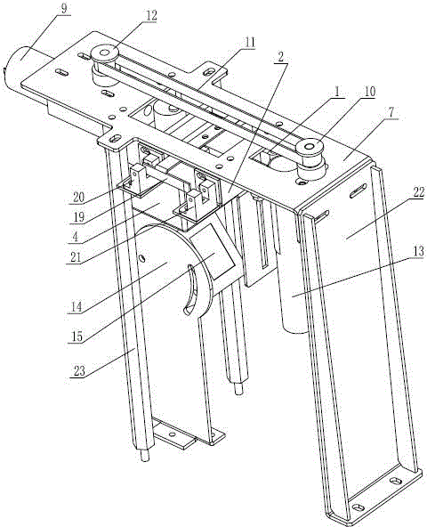
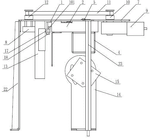
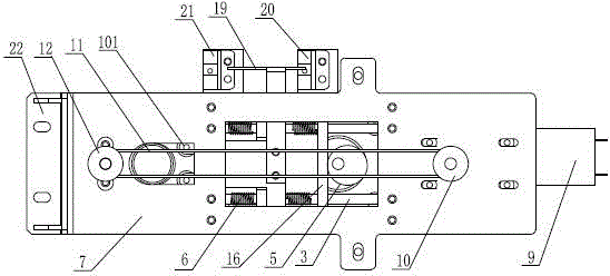
[0024] See figure 1 , figure 2 , image 3 , the present invention as figure 1 As shown, including clamping mechanism, rotating mechanism and scanner 15, wherein:

[0025] The clamping mechanism includes a clamping part 1, the front end of the clamping part 1 has a concave opening, and both sides of the concave opening are cylindrical clamping ends 101, and the cylindrical clamping end 101 includes a bearing 17, and the upper and lower two A bearing 17 is installed on the cylindrical hole of the head of the clamping part 1 through a pin 18, the clamping part 1 is slidingly matched with the guide rod 3 in the base 2, the clamping motor 4 is installed on the base 2, and the clamping motor 4 The output shaft and the cam 5 are coaxially fixed, and the cam 5 pushes the clamping part 1 to move on the guide rod 3. A spring 6 is arranged betwe...


PUM


Abstract

A rotation device for test tube scanning comprises a clamping mechanism, a rotation mechanism and a scanner. The clamping mechanism comprises a clamping part. An inward concave opening is formed at the front end of the clamping part. Two sides of the inward concave opening are both cylinder claming ends. The clamping part is matched with a guiding rod in a base seat in a sliding mode. A clamping motor is arranged on the base seat. An output end of the clamping motor is coaxially and fixedly connected with a cam which pushes the clamping part to move along the guiding rod. A spring is arranged between the clamping part and one side, close to the cylinder clamping ends, of the base seat and is arranged on the guiding rod in a sleeved mode. The base seat is fixed on a supporting plate. The rotation mechanism comprises a roller, wherein the roller drives a test tube to rotate and is arranged on the front end of the clamping part and driven to rotate by a rotation motor. An output end of the rotation motor is connected with a driving belt wheel in a transmission mode. The driving belt wheel drives a driven belt wheel to rotate through a belt connected on the driving belt wheel in a winding mode. The driven belt wheel is coaxially and fixedly connected with the roller. The rotation motor is arranged on the supporting plate. The rotation device for the test tube scanning can achieve rapid and continuous scanning of barcodes on a batch of test tubes.

Description

technical field [0001] The invention relates to the technical field of reagent detection and analysis instruments, in particular to a device capable of rotating a test tube so as to facilitate scanning of barcodes on it. Background technique [0002] In batch reagent detection and analysis tests, in order to facilitate identification and statistics, barcodes are usually pasted on the test tubes, and then the barcodes on the test tubes are scanned by the scanning device, and the subsequent detection and analysis can only be performed after the barcode information is successfully read. Operation. At present, the methods for barcode scanning of test tubes are mainly manual scanning and mechanical scanning. Manual scanning has a large workload and low efficiency, and it is easy to miss or make wrong statistics. However, some existing mechanical scanning does not have the test tube rotation function. If the position of the barcode does not correspond to the position of the scann...

Claims


Application Information

Patent Timeline
Patent Type & Authority Patents(China)
IPC IPC(8): G06K7/10
Inventor 蔡云飞潘一新戴方兴丁林先
Owner 无锡研中科技有限公司
Learn More