
Electron-optical device with inverted magnetic domain and electron-optical unit utilizing said device

A technology of electronic optics and devices, applied in optics, nonlinear optics, instruments, etc., can solve problems such as no zoom lens

Inactive Publication Date: 2004-04-28
SONY CORP
View PDF0 Cites 0 Cited by
  • Summary
  • Abstract
  • Description
  • Claims
  • Application Information

AI Technical Summary

Problems solved by technology

In the prior art, there is no optical converter with both high speed and high resolution
[0009] Also, there is no single zoom lens or mirror that can be switched on and off

Method used


Image

  • Electron-optical device with inverted magnetic domain and electron-optical unit utilizing said device
  • Electron-optical device with inverted magnetic domain and electron-optical unit utilizing said device
  • Electron-optical device with inverted magnetic domain and electron-optical unit utilizing said device

Examples


Embodiment Construction

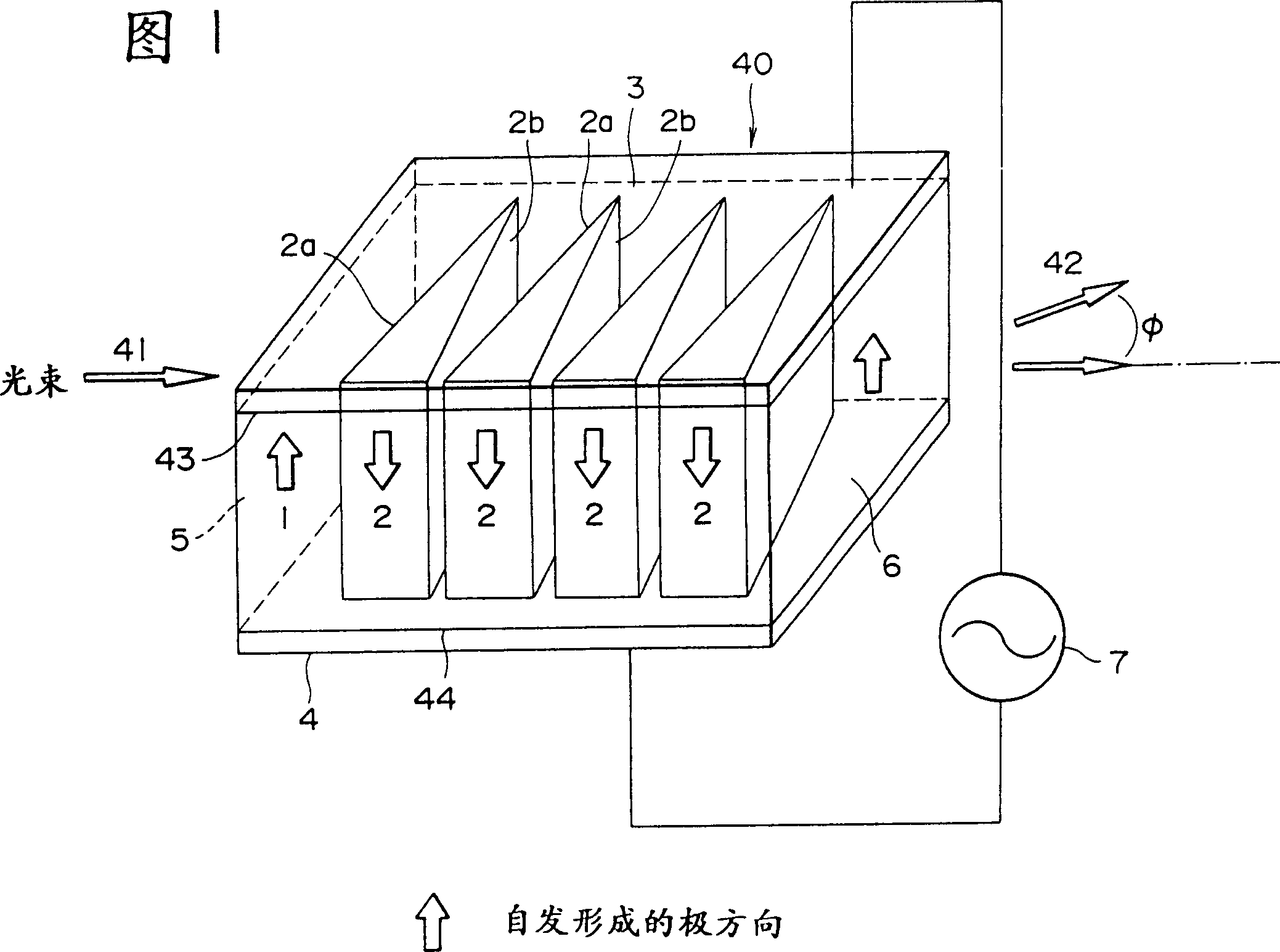
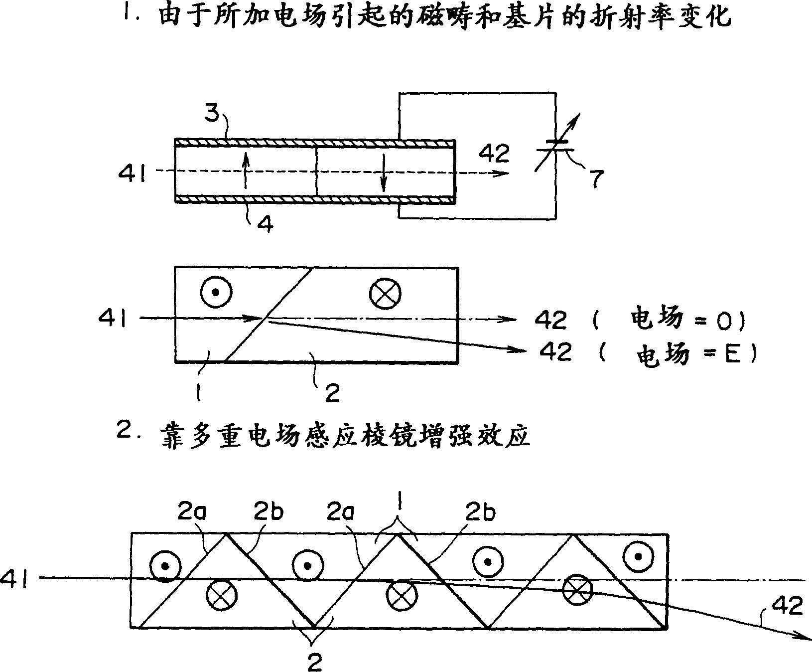
[0036] In the electro-optical device of the present invention, it is desirable to have at least two domain walls with opposed inversion domains horizontally traversed by a propagating light beam, on each of which the light beam has a different angle of incidence, whereby The light beam is deflected according to a voltage applied between electrodes formed on two opposing major surfaces of a substrate.

[0037] It is particularly desirable for the mirror described above that the domain walls are stacked at a predetermined period so that the light beam is incident at a predetermined angle by applying a voltage between electrodes on two opposing major surfaces of the substrate to change the direction of propagation of the beam.

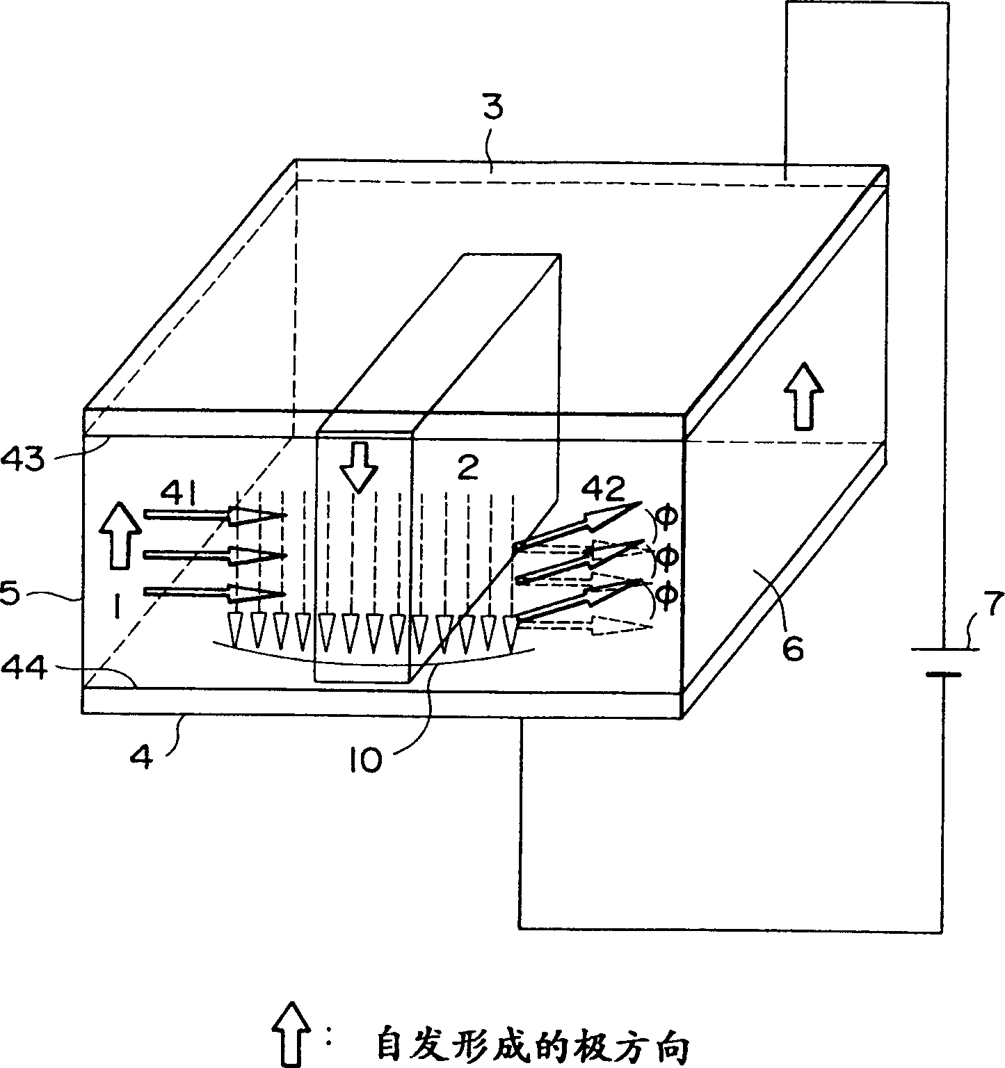
[0038] Furthermore, it is particularly advantageous for the aforementioned variable focal length lens that in the direction of propagation of the beam there are at least two domain walls with a convexity and a concavity in this direction, passing on two o...


PUM

PropertyMeasurementUnit
refractive indexaaaaaaaaaa

Abstract

An electro-optical device such as an optical deflector comprising a ferro-electric substrate, electrodes provided on principal surfaces of this substrate and an inverted domain having a polygonal, e.g. triangular shape formed in the substrate, at least one of the domain walls of these domains being effectively perpendicular to the principal surfaces of the substrate, and a light beam passing through at least two of the domain walls, thus permitting fast random access, wide deflection angle and high resolution.

Description

technical field [0001] This invention relates to electro-optical devices, and more particularly to devices such as light deflectors which utilize electro-optical effects. Background technique [0002] Devices known in the art that utilize electro-optical effects include light deflectors and light modulators. Devices that do not take advantage of this effect include lenses and mirrors. [0003] Light deflectors commonly used to electronically deflect light beams include galvanometers, rotating polygon mirrors, and rotating holographics. Since all these deflectors are electromechanical deflection devices, they are not suitable for short-term random access, although they also allow high-resolution and relatively high-speed continuous scanning. [0004] Other high-speed deflectors exploit Bragg diffraction by means of an acousto-optic diffraction grating. These have access times on the order of microseconds, however they can only produce small deflection angles, they are limi...

Claims


Application Information

Patent Timeline
Patent Type & Authority Patents(China)
IPC IPC(8): G02F1/05G02F1/03G02F1/29G02F1/355
CPCG02F1/0322G02F1/3558G02F1/29G02F1/0305G02F1/0316G02F1/05
Inventor 山田正裕
Owner SONY CORP
Learn More