High capacity card case fixed type automatic card sender
An automatic card-issuing, fixed-type technology, applied in instruments, ticketing equipment, etc., can solve the problem that the toll management department is difficult to accurately know the driving route of the vehicle, the dual-frequency reading and writing function IC card manufacturing technology is backward, and the impact of the separation of the interests of road network owners, etc. Problems, to achieve the effect of low manufacturing cost, good applicability, and high card output rate
- Summary
- Abstract
- Description
- Claims
- Application Information
AI Technical Summary
Problems solved by technology
Method used
Image
Examples
Embodiment 1
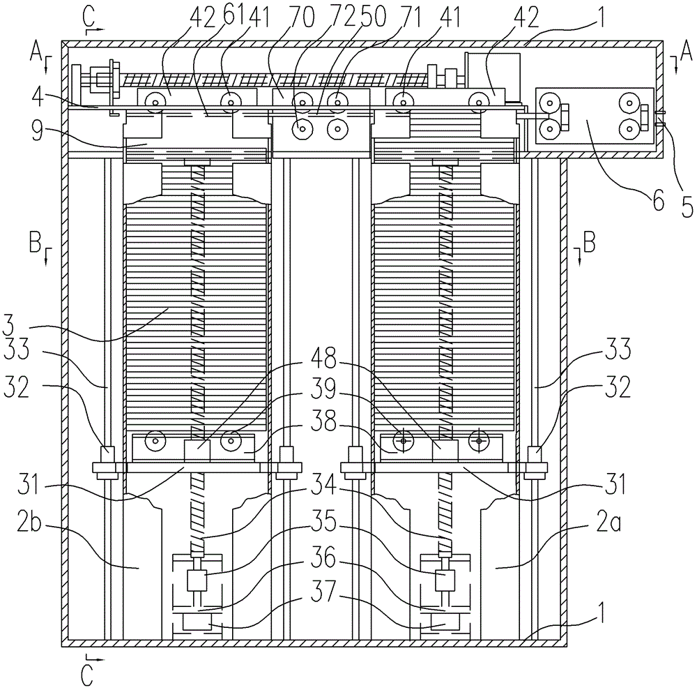
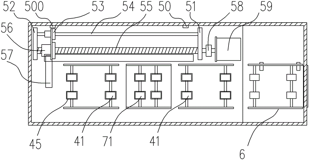
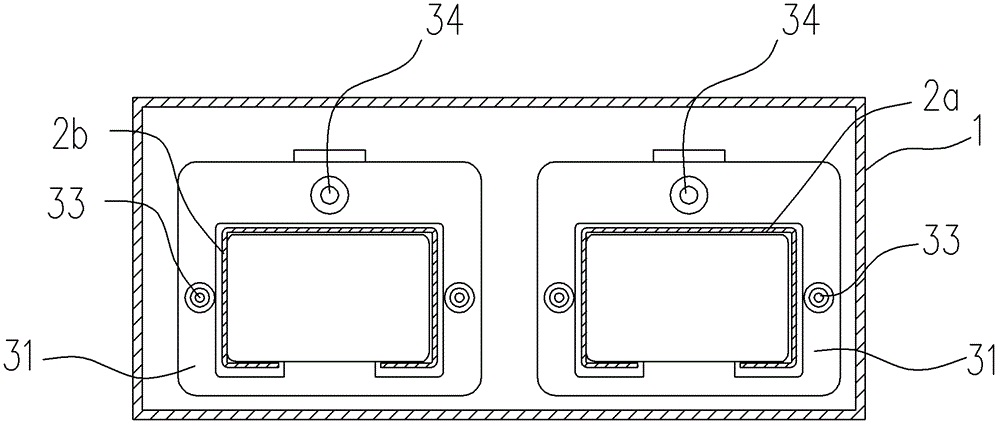
[0032] Such as Figure 1~4 As shown, it is a large-capacity card box fixed automatic card issuing machine of the present invention, including a casing 1, a frame arranged in the casing 1, a card box vertically installed in the casing 1 for containing cards 3, The card feeding mechanism that can move longitudinally along the card box, the card rolling mechanism 6 that sends the card to the card outlet 5, the card dial mechanism and the driving mechanism. The top of the card box 2a, 2b is provided with a limit mechanism for card 3 limit, and the card dial mechanism is arranged on the side of the top of the card box 2a, 2b as a common part of the card box 2a, 2b, on the card box 2a, 2b The side portion is correspondingly provided with the elongated card-pull hole for the card-pull mechanism to stretch into the card box 2a, 2b to move the card 3. The width of the card-pull hole is greater than 0.6mm and less than 6mm. Card box 2a, 2b front and rear upper parts are also provided w...
Embodiment 2
[0046] The difference between this embodiment (not shown in the figure) and Embodiment 1 is (for convenience of explanation, still adopt the statement of the card box 2a, 2b in the figure): there is no space between the card box 2a, 2b, that is, the card box 2a and 2b are close to each other, so there is no need to set up a card conveying mechanism. When this embodiment is working, after the cards are loaded, the card feeding mechanism of the 2b card box remains in the lower position, and the card dial of the card pulling mechanism moves to the bottom of the card box 2a. At the top, the card feeding mechanism of the card box 2a moves, and the cards in the card box 2a rise to the opening on the top surface of the card box, and the card dial is pulled to realize card issuance, and the cards are pushed to the card rolling mechanism by the card dial to be issued; After the cards in the box 2a have been sent out, the card feeding mechanism of the card box 2a remains in the upper pos...
Embodiment 3
[0048] Such as Figure 5 As shown, the difference between this embodiment and Embodiment 1 is that the card supporting plate 31 of the card feeding mechanism is composed of a vertically arranged card feeding screw rod 34 and a pair of vertically arranged screw rods 34 that apply force upward to the card supporting plate 31. The tension springs 8 are jointly driven, and the upper ends of the tension springs 8 are respectively connected with the upper frame in the casing 1 , and the lower ends are respectively connected with the card supporting plate 31 .
PUM
 Abstract
Description
Claims
Application Information
 - R&D
- Intellectual Property
- Life Sciences
- Materials
- Tech Scout
- Unparalleled Data Quality
- Higher Quality Content
- 60% Fewer Hallucinations
Browse by: Latest US Patents, China's latest patents, Technical Efficacy Thesaurus, Application Domain, Technology Topic, Popular Technical Reports.
© 2025 PatSnap. All rights reserved.Legal|Privacy policy|Modern Slavery Act Transparency Statement|Sitemap|About US| Contact US: help@patsnap.com


