Waste heat power generation method of Stirling engine

A Stirling engine and waste heat power generation technology, which is applied in the direction of machines/engines, hot gas variable capacity engine devices, mechanical equipment, etc., can solve the problems of unsuitable utilization of scattered waste heat sources, high temperature of waste heat sources, and low power quality. Achieve the effect of improving energy utilization rate, small overall investment, and high heat-power conversion efficiency

Inactive Publication Date: 2012-07-04
INST OF ENGINEERING THERMOPHYSICS - CHINESE ACAD OF SCI
View PDF4 Cites 9 Cited by
  • Summary
  • Abstract
  • Description
  • Claims
  • Application Information

AI Technical Summary

Problems solved by technology

[0003] The purpose of the present invention is to solve the technical defects of the existing waste heat power generation method that the equipment is huge, the heat source of waste heat is required to be high in temperature, it is not suitable for the utilization of scattered waste heat heat source, additional heating is required, and the generated power is of low grade, and it provides a Stirling engine waste heat Power generation method, the overall equipment is compact, the temperature of the heat source is low, no additional heat source is required, the economy is good, the waste heat required by the monomer is small, and the power generation grade is high

Method used


Image

  • Waste heat power generation method of Stirling engine
  • Waste heat power generation method of Stirling engine
  • Waste heat power generation method of Stirling engine

Examples


Embodiment 1

[0023] Embodiment 1: The heat absorber 1 of the Stirling engine 4 is placed in the flue of a power plant boiler or an industrial boiler, and the heat absorber 1 is placed near the front end of the heat collecting tube 7 without affecting the operation and performance of the boiler , heat-collecting pipe 7 is wrapped with thermal insulation material 6, and Stirling engine 4 except heat absorber 1, regenerator 2, cooler 3 and other components and generator 5 are fixed on the outside of the flue. According to the boiler flue gas temperature and thermal power, multiple heat absorbers 1 of Stirling engines 4 can be arranged in the flue to realize the comprehensive utilization of flue gas at different temperature steps.

Embodiment 2

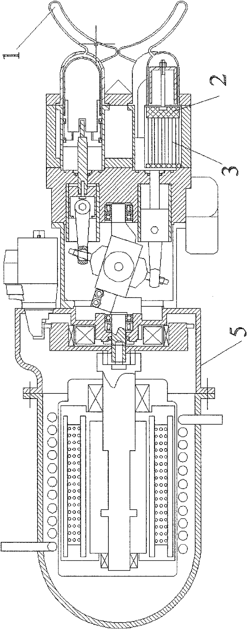
[0024] Embodiment 2: The steam discharged from the final stage blades when the steam turbine is working is used as the heat source 8, and the heat collecting pipe 7 wrapped with the heat insulating material 6 is led to the heat absorber 1 of the Stirling engine 4, in order to strengthen the steam and heat absorber 1 heat exchange effect, the heat absorber 1 of the Stirling engine 4 is arranged in a gas collecting chamber 9 connected with the heat collecting pipe 7, and the steam heats the inner work of the heat absorber 1 of the Stirling engine 4 in the gas collecting chamber 9 quality, pushing the Stirling engine 4 to work. In order to prevent water vapor from condensing in the gas collecting chamber 9 and causing corrosion on the surface of the heat absorber 1, the heat absorber 1 of the Stirling engine 4 is designed to extend from the top of the gas collecting chamber 9, and to be formed with the wall of the gas collecting chamber 9. Sealing, the regenerator 2 of the Stirli...

Embodiment 3

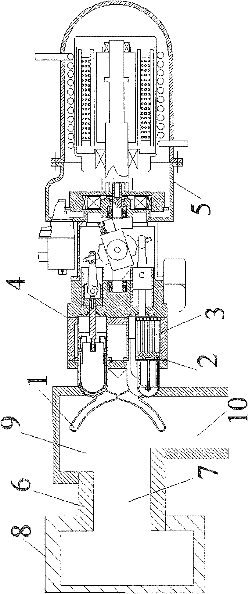
[0025] Embodiment 3: With the exhaust gas of the internal combustion engine as the heat source 8, the heat absorber 1 of the Stirling engine 4 extends from the top of the gas collection chamber 9 and is placed in the middle of the gas collection chamber 9, and the exhaust gas of the internal combustion engine is equipped with heat insulating material 6 from the outside The heat collecting pipe 7 leads to the gas collecting chamber 9, heats the heat absorber 1 of the Stirling engine 4, and promotes the work of the Stirling engine 4. On the outside of the road, the Stirling engine 4 drives the generator 5 to generate electricity through a coupling. The flue gas of the internal combustion engine after heat exchange is discharged through the exhaust pipe 10 connected with the gas collection chamber 9 .


PUM


Abstract

The invention discloses a waste heat power generation method of a Stirling engine, relating to a waste heat power generation technology. A heat absorber of the Stirling engine is arranged in a gas-collecting cavity, and the top of the heat absorber is vertical to an incoming direction of waste heat. The waste heat power generation method comprises the following steps: helium or hydrogen is filled in the heat absorber to be as an acting medium of the Stirling engine and drives a piston of the Stirling engine to move forth and back to generate mechanical energy after being heated to expand, and the Stirling engine drives a power generator connected with the Stirling engine to generate power; and waste heat gas in the gas-collecting cavity heats the helium or hydrogen in the heat absorber and then is exhausted into environment. A device for converting the waste heat into the mechanical energy through the Stirling engine is a special component applied to the waste heat power generation method disclosed by the invention, and comprises the Stirling engine, heat collecting tubes, the gas-collecting cavity and the power generator. According to the waste heat power generation method of the Stirling engine, disclosed by the invention, heat is converted to the mechanical energy, and the mechanical energy is also converted to electric energy, thus waste heat power generation with the advantages of compact structure, good economical efficiency, convenience for using and no need of additional heating is realized; and the conversion from low-grade waste heat to high-grade electric energy is realized.

Description

technical field [0001] The invention relates to the technical field of waste heat power generation, and relates to a Stirling engine waste heat power generation method, which uses waste heat from boiler exhaust gas, steam turbine exhaust steam, internal combustion engine exhaust gas, and gas turbine exhaust gas to generate mechanical energy, and then drives a generator to generate electricity. Background technique [0002] At present, there are two main forms of waste heat power generation from boiler exhaust, steam turbine exhaust, internal combustion engine exhaust and gas turbine exhaust: one is to reheat the steam or use the heat carried by the flue gas to heat water to generate high-temperature and high-pressure steam to drive the steam turbine to work and drive power generation generator. The disadvantages of this technology are: the equipment of the whole system is relatively large, the pipeline layout is complicated, the investment cost is relatively high, and only t...

Claims


Application Information

Patent Timeline
Patent Type & Authority Applications(China)
IPC IPC(8): F01K27/02F02G1/043F02G1/057
Inventor 唐大伟杜景龙李铁周天
Owner INST OF ENGINEERING THERMOPHYSICS - CHINESE ACAD OF SCI
Why Eureka
Try Eureka