Drive circuit, dimmer controller and method for electrically controlling light-emitting diode (LED) light source

A dimming controller and drive circuit technology, which is applied in the direction of electric lamp circuit layout, light source, electric light source, etc., can solve the problems of cost increase, and achieve the effects of cost saving, comfortable user experience, and avoiding sudden changes in brightness

Inactive Publication Date: 2012-07-04
AOTU ELECTRONICS WUHAN
View PDF5 Cites 27 Cited by
  • Summary
  • Abstract
  • Description
  • Claims
  • Application Information

AI Technical Summary

Problems solved by technology

This traditional LED drive circuit 200 needs to use some special device to adjust the brightness of the LED chain 106, such as using a specially designed switch with an adjustment button or a switch that can receive remote control signals, resulting in increased costs.

Method used


Image

  • Drive circuit, dimmer controller and method for electrically controlling light-emitting diode (LED) light source
  • Drive circuit, dimmer controller and method for electrically controlling light-emitting diode (LED) light source
  • Drive circuit, dimmer controller and method for electrically controlling light-emitting diode (LED) light source

Examples


Embodiment Construction

[0036] Detailed reference will be given below to examples of the present invention. Although the present invention has been illustrated and illustrated by these embodiments, it should be noted that the present invention is not limited to these embodiments. On the contrary, the invention covers all alternatives, modifications and equivalents which are within the spirit and scope of the invention as defined by the appended claims.

[0037] In addition, in order to better illustrate the present invention, numerous specific details are given in the specific embodiments below. It will be understood by those skilled in the art that the present invention may be practiced without these specific details. In other instances, well-known methods, procedures, components and circuits have not been described in detail so as not to obscure the gist of the present invention.

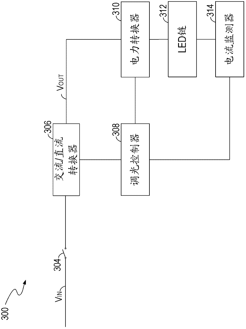
[0038] image 3Shown is a schematic diagram of a light source driving circuit 300 according to an embodiment of the...


PUM


Abstract

The invention discloses a drive circuit, a dimmer controller and a method for electrically controlling a light-emitting diode (LED) light source. The drive circuit comprises a transformer, a switch controller and a dimmer controller. The transformer comprises a primary winding which is used for receiving the input electric energy from an alternating current/direct current converter and an auxiliary winding which provides the output electric energy for the LED light source. The switch controller is connected between an optical coupler and the primary winding, and is used for receiving a feedback signal which indicates the target value of the current which passes by the LED light source, and controlling the input electric energy of the primary winding according to the feedback signal. The dimmer controller is connected with the auxiliary winding, and is used for receiving a switch monitoring signal which indicates the motion of a power switch, and adjusting the output electric energy of the transformer through adjusting the feedback signal according to the switch monitoring signal. According to he invention, the brightness of the LED light source can be controlled without using other dimming devices, and accordingly, the cost is saved.

Description

technical field [0001] The invention relates to a light source driving circuit, in particular to a driving circuit, a dimming controller and a method for controlling electric energy of an LED light source. Background technique [0002] In recent years, new light sources such as light-emitting diodes (LEDs) have advanced both in materials and manufacturing. LED has the characteristics of high efficiency, long life, bright colors, etc., and can be used in the fields of automobiles, computers, communications, military and daily necessities. For example, LED lamps can replace traditional incandescent lamps as lighting sources. [0003] figure 1 Shown is a schematic diagram of a conventional LED driving circuit 100 . LED driver circuit 100 utilizes LED chain 106 as a light source. LED chain 106 includes a plurality of LEDs connected in series. The power converter 102 converts the input voltage Vin to a desired DC output voltage Vout for powering the LED chain 106 . A switch...

Claims


Application Information

Patent Timeline
Patent Type & Authority Applications(China)
IPC IPC(8): H05B37/02
Inventor 阎铁生林风李友玲郭清泉
Owner AOTU ELECTRONICS WUHAN
Why Eureka
Try Eureka