LED dimming driving device and dimming LED lamp

A dimming drive, LED lamp technology, applied in lighting devices, lighting device components, light sources, etc., can solve the problems of inconvenience of increasing engineering installation, inconvenient regulation, and inability to save control costs, etc., and achieve powerful functions and structure. Simple, easy-to-promote effects

Inactive Publication Date: 2013-11-06
广东百正节能服务有限公司
View PDF2 Cites 0 Cited by
  • Summary
  • Abstract
  • Description
  • Claims
  • Application Information

AI Technical Summary

Problems solved by technology

[0004] Even if there is another control method that does not use a remote controller to control the LED lamp, but directly connects the control circuit board to the drive circuit of the LED lamp through wires, including the key board of the control circuit board fixed on the wall or other objects, but Such a control method cannot save the control cost very much, and it increases the inconvenience of engineering installation, and on the other hand, it also brings inconvenience to users in regulation.

Method used


Image

  • LED dimming driving device and dimming LED lamp
  • LED dimming driving device and dimming LED lamp
  • LED dimming driving device and dimming LED lamp

Examples


Embodiment 1

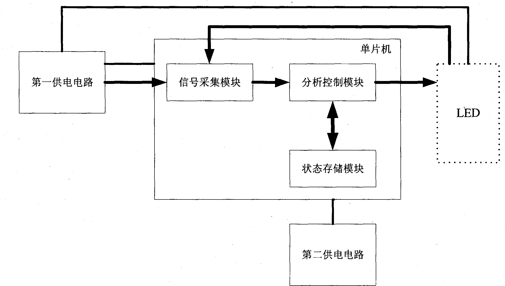
[0024] like figure 1 As shown, this embodiment relates to an LED dimming driving device, which includes a first power supply circuit, a single-chip microcomputer and a second power supply circuit, and the single-chip microcomputer is used to control the first power supply circuit to supply power to the LED. The first power supply circuit is also used to supply power to the single-chip microcomputer. The second power supply circuit is used to supply power to the single-chip microcomputer after the first power supply circuit stops supplying power. The first power supply circuit includes a step-down rectifier module for converting 110V to 220V, The 50HZ mains voltage is step-down filtered and rectified into low-voltage pulsed direct current. The second power supply circuit is a temporary power supply circuit, including an electric energy storage module. The electric energy storage module includes electric energy charging and discharging elements for the electric energy storage mod...

Embodiment 2

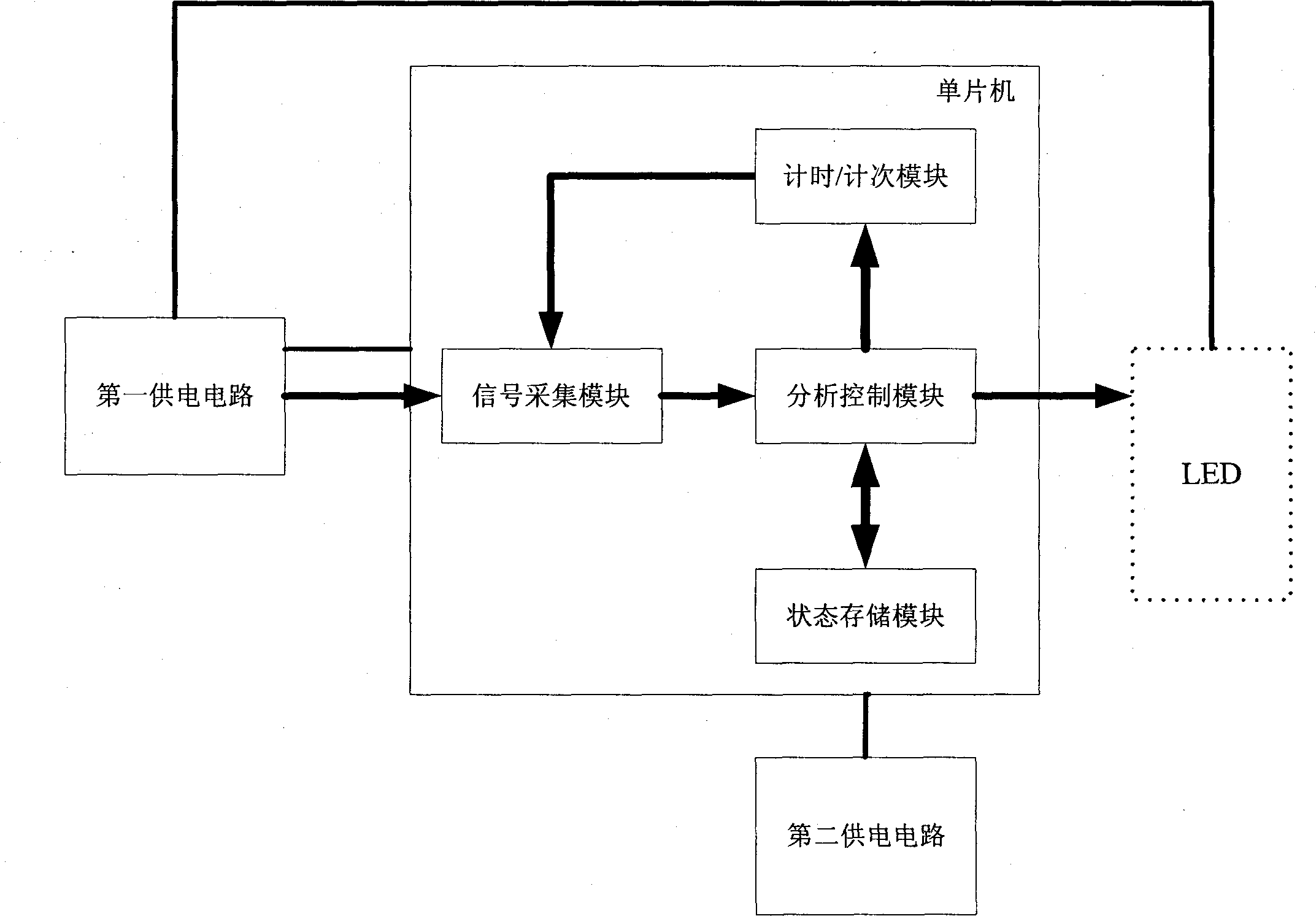
[0030] like figure 2As shown, this embodiment relates to another LED dimming driving device. The LED dimming driving device includes a first power supply circuit, a single-chip microcomputer and a second power supply circuit. The single-chip microcomputer is used to control the first power supply circuit to supply power to the LED. The first power supply circuit is also used to supply power to the single-chip microcomputer, and the second power supply circuit is used to supply power to the single-chip microcomputer after the first power supply circuit stops supplying power. The first power supply circuit includes a step-down rectifier module for converting 110V to 220V , the 50HZ mains voltage is step-down filtered and rectified into low-voltage pulsed direct current, the second power supply circuit is a temporary power supply circuit, including an electric energy storage module, and the electric energy storage module includes electric energy charging and discharging elements ...

Embodiment 3

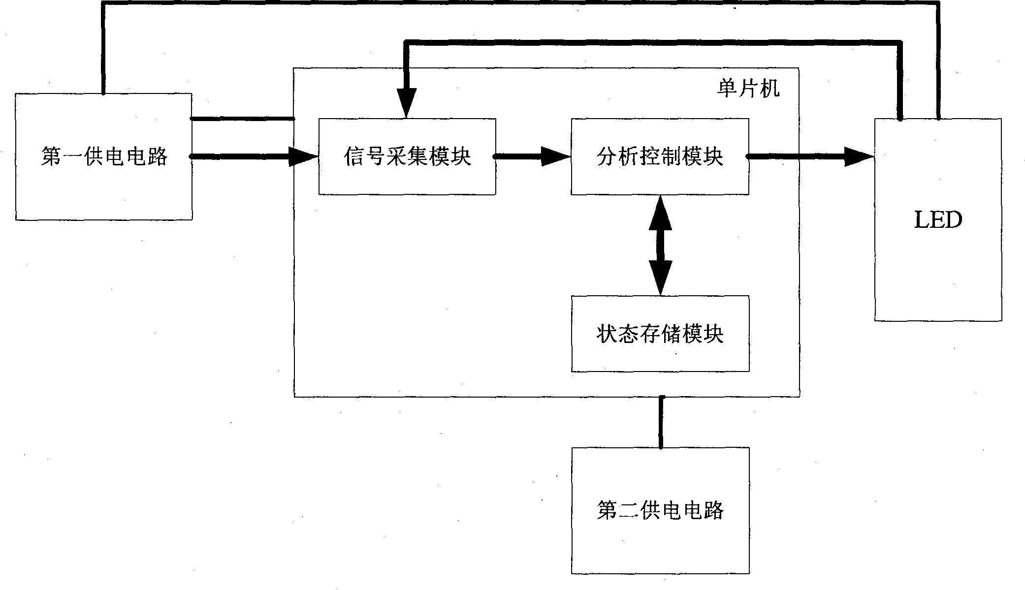
[0038] like image 3 As shown, the present invention also provides an LED dimming lamp, which includes the LED dimming driving device as described in Embodiment 1 and an LED connected to the LED dimming driving device. The LED dimming lamp is connected with an on-off switch, and connected with 110V-220V 50HZ AC mains.


PUM


Abstract

The invention belongs to the technical field of lighting lamp control, and relates to an LED dimming driving device and a dimming LED lamp with the same; and the LED dimming driving device and an on-off switch control and regulate the brightness or color changes of the LED lamp. The invention provides the LED dimming driving device which comprises a first power supply circuit, a single-chip microcomputer and a second power supply circuit; the single-chip microcomputer is used for controlling the first power supply circuit to supply power to the LED and supplying power to the single-chip microcomputer; the second power supply circuit is used for supplying power to the single-chip microcomputer after the first power supply circuit stops supplying power; and the single-chip microcomputer is used for acquiring and analyzing the on / off signal of the first power supply circuit, and selecting and outputting an LED control signal which corresponds to the on / off signal.

Description

【Technical field】 [0001] The invention belongs to the technical field of illumination lamp control, and relates to an LED dimming driving device and a dimming LED lamp provided with the dimming driving device. The LED dimming driving device controls and adjusts the brightness or color of the LED lamp together with an on-off switch. Variety. 【Background technique】 [0002] Compared with ordinary fluorescent lamps or tungsten-halogen lamps, the advantages of LED lamps are not only their high luminous efficiency and long service life, but also their good color rendering, which can display a variety of different colors. In the prior art, the color control of LED lighting lamps is mainly controlled by a remote controller. The remote controller is equipped with a control circuit board and control buttons. The control buttons are used to select different color change drivers for LED lights, and the control commands are sent wirelessly. To the LED light driving circuit at the recei...

Claims


Application Information

Patent Timeline
Patent Type & Authority Patents(China)
IPC IPC(8): H05B37/02F21S2/00F21V23/00F21Y101/02
Inventor 许波
Owner 广东百正节能服务有限公司
Why Eureka
Try Eureka