Device and method for fitting sacks

A technology of equipment and valve pockets, which is applied in the field of equipment for inserting and placing bags, can solve the problems of difficulty in straightening independent valve pockets and difficulty in inserting and placing valve pockets, and achieves high insertion and placement efficiency

Active Publication Date: 2012-07-11
HAVER & BOECKER
View PDF6 Cites 5 Cited by
  • Summary
  • Abstract
  • Description
  • Claims
  • Application Information

AI Technical Summary

Problems solved by technology

However, they are less than ideal for automated fill-and-discharge systems because the flexibility of the valve pocket makes

Method used


Image

  • Device and method for fitting sacks
  • Device and method for fitting sacks
  • Device and method for fitting sacks

Examples


Embodiment Construction

[0062] Some exemplary embodiments of the device according to the invention will be described below with reference to the accompanying drawings.

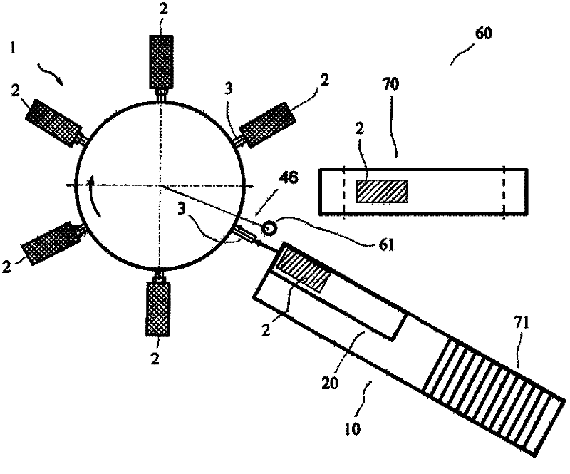
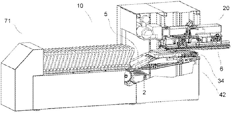
[0063] figure 1 A simplified top view of a packaging system 60 comprising a rotary packaging machine 1 and a placement device 10 as well as an unloading conveyor 70 is shown.

[0064] The packaging machine 1 is used for filling valve pockets 2 and, in the presently shown embodiment, comprises six circumferentially distributed filling openings 3 , of which five filling openings 3 are arranged with valve pockets 2 .

[0065] The packaging machine 1 is shown in the insertion position. The angle sensor 61 has previously sensed the next filling opening 3 rotating past the predetermined angular position 46 , thus triggering the next insertion operation. Instead of using sensors for the insertion device 10 , it is also conceivable to use sensors on the packaging machine for detecting the predetermined angular position 46 .

[0066] The i...


PUM


Abstract

The device has a gripping unit and an insertion unit for gripping sacks The insertion unit is transferred in a partly hanging position for insertion. An alignment unit is provided to ensure defined vertical alignment of the sacks to be inserted. A storage table is provided for retaining a flatly lying sack bundle. The alignment unit comprises a blower with an air nozzle. The blower outputs partly upward aligned air blast. The alignment unit aligns the sacks against a system unit with an upper stop. An independent claim is also included for a method for insertion of valve sacks on a filler neck of a pack machine.

Description

technical field [0001] The invention relates to a device and a method for inserting a bag, in particular a device and a method for inserting a valve bag on a filling opening, especially of a rotary packaging machine. Background technique [0002] Various devices and methods are known in the prior art for inserting valve bags onto the filling ports of rotary packaging machines. Rotary packaging machines with 4, 6, 8, 10, 12 or 16 or other numbers of filling openings are also known in the prior art. They are used to efficiently fill many different kinds of materials. For example, bulk materials such as cement are often packaged with rotary packaging machines. Today's packaging machines can have high filling speeds, wherein for example one or more bags are filled per second. [0003] In order to realize the automatic operation of this packaging machine, the valve bag is inserted or thrown onto the filling port of the rotary packaging machine by means of an automatic insertio...

Claims


Application Information

Patent Timeline
IPC IPC(8): B65B43/26
CPCB65B43/12B65B43/262B65B43/18
Inventor C・莱姆福特
Owner HAVER & BOECKER
Why Eureka
Try Eureka