Mechanical and electronic composite lock

A mechatronic and compound lock technology, which is applied to locks controlled by non-mechanical transmission, building locks, buildings, etc., can solve the problems of solenoid valve locks that are difficult to open, have no emergency opening function, and get out of the working position, etc., so as to achieve a reasonable and practical overall structure , Protect the electromagnet core, enhance the effect of strength

Inactive Publication Date: 2014-04-30
宁波永发智能安防科技有限公司
View PDF8 Cites 2 Cited by
  • Summary
  • Abstract
  • Description
  • Claims
  • Application Information

AI Technical Summary

Problems solved by technology

[0004] The existing mechanical and electronic composite locks have the following disadvantages: 1. The electromagnet core is in direct contact with the skateboard. Once the handle is turned too hard, the skateboard will directly hit the electromagnet core, damage the electromagnet core or directly slide over the electromagnet core , so that the door is opened, causing potential safety hazards; 2. It is easy to be opened by vibration. The existing electromagnetic valve lock is held in the working position because its electromagnetic core is stretched out through a spring (generally the elastic force is small, and it cannot be sucked up if it is too large). The box body, that is, lift one side of the box body, put one hand on the handle position, and control the drop of the box body with the other hand, and turn the handle at the moment of landing. There is a downward force in the relationship, and it will go down a short distance, thus leaving the working position, causing a safety hazard; 3. The existing mechanical and electronic composite lock has no emergency opening function, and it is not easy to open after the electromagnetic valve lock is damaged.

Method used


Image

  • Mechanical and electronic composite lock
  • Mechanical and electronic composite lock
  • Mechanical and electronic composite lock

Examples


Embodiment Construction

[0023] The present invention will be further described in detail below in conjunction with the accompanying drawings and embodiments.

[0024] Such as Figure 1~5 Shown is a preferred embodiment of the present invention.

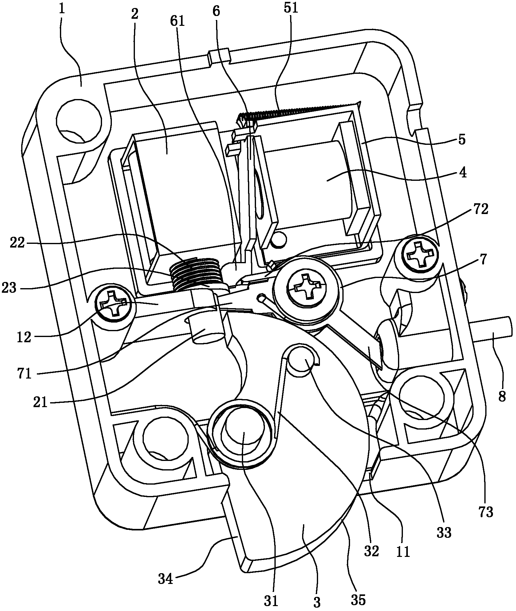
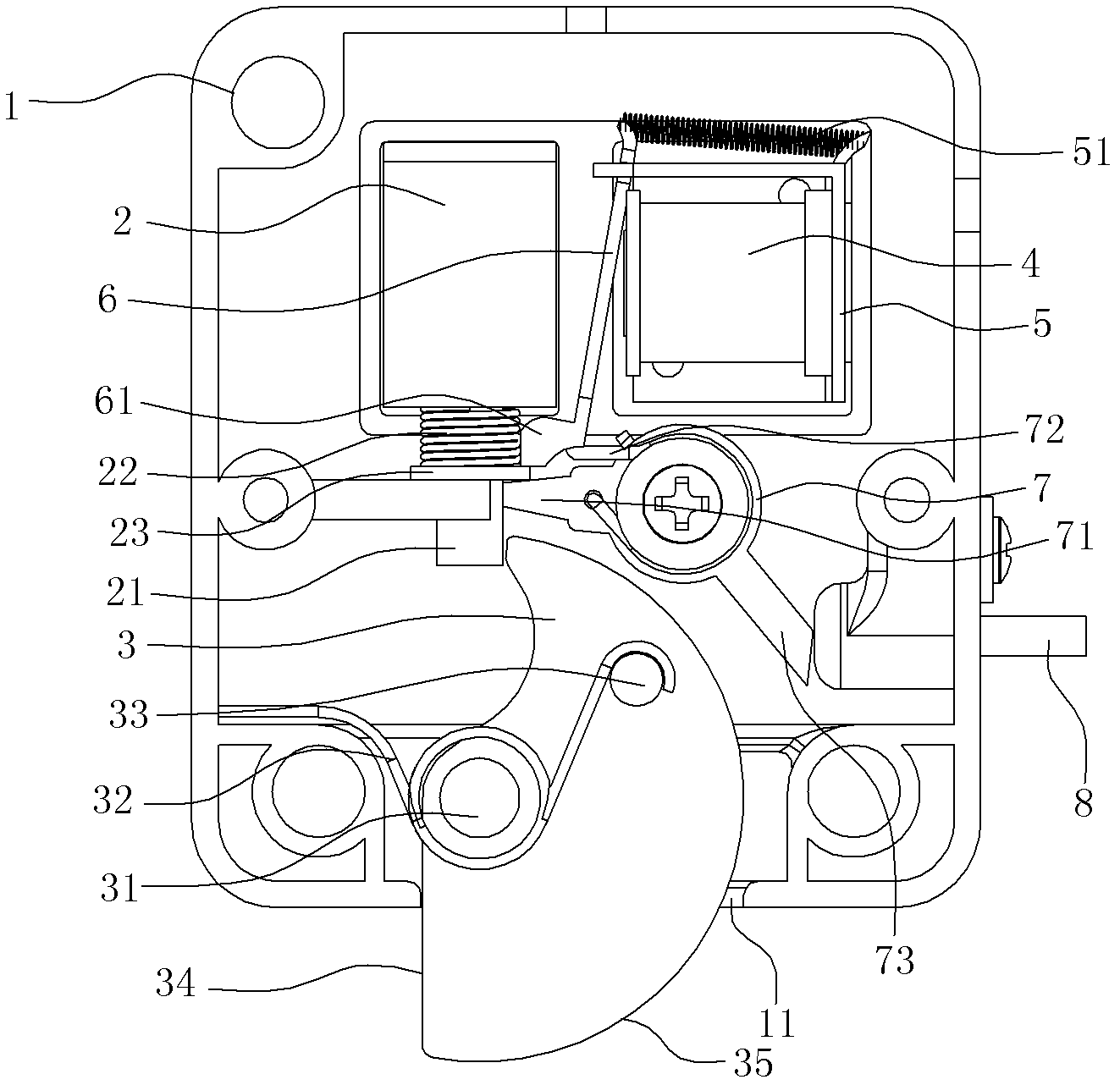
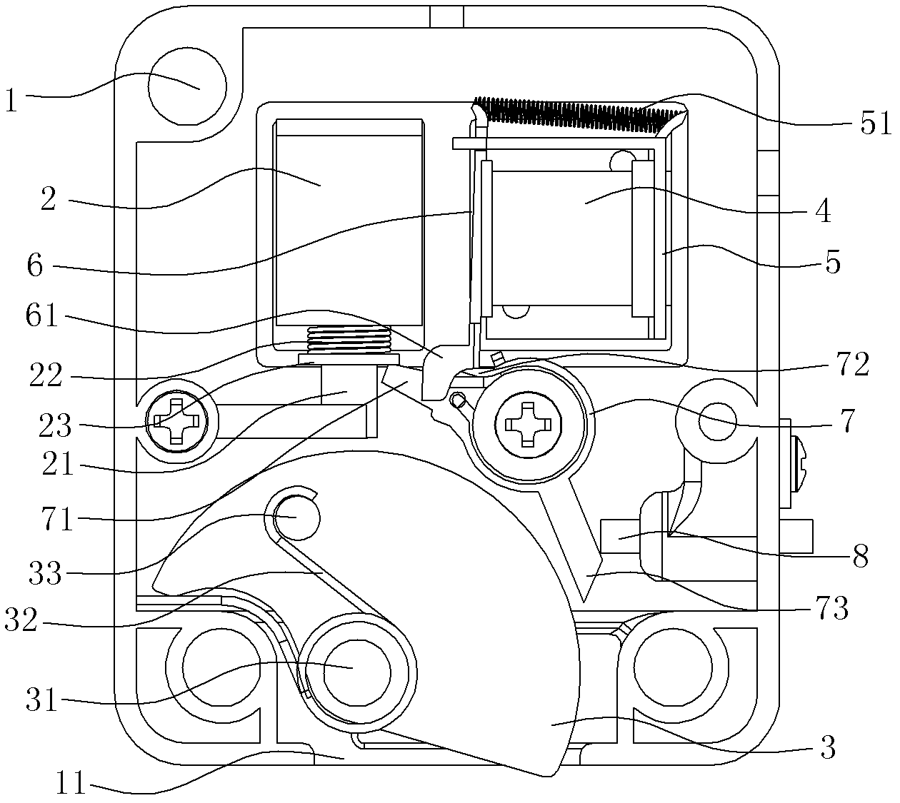
[0025] A mechanical and electronic composite lock, comprising a lock case 1, the lock case 1 has an upper case and a lower case connected together by screws, and the lock case 1 is provided with a solenoid valve lock 2 with a retractable electromagnet core 21, and the electromagnet The core 21 is covered with a spring 22 and is fixed with a retaining ring 23. The spring 22 acts on the retaining ring 23 and keeps the electromagnet core 21 moving downward; The notch 121 through which the magnet core 21 passes, the retaining ring 23 is in contact with the upper end surface of the baffle plate 12 when the electromagnet core 21 is kept stretched out.

[0026] The lock housing 1 is connected with a deadbolt plate 3 through a rotating shaft 31 in rotation. The de...


PUM


Abstract

A mechanical and electronic composite lock comprises a lock case and an electromagnetic valve lock with an electromagnet core. The electromagnet core is sleeved with a spring and fixed with a retainer ring. The mechanical and electronic composite lock is characterized in that the inside of the lock case is rotatably connected with a lock bolt plate via a rotating shaft, and the rotating shaft is sleeved with a first torsional spring; an electromagnet which is arranged transversely is further disposed in the lock case via a base, the middle of a crow plate is connected to the upper side of the base, the crow plate can deflect left and right, and the upper end of the crow plate is connected with the right of the base via a tension spring; and when the lock bolt plate extends out of the lock case, the upper end of the lock bolt plate matches with a gear position of the electromagnet core extending outwards so as to stop the lock bolt plate from rotating to retract into the lock case, and the lower end of the crow plate matches with the retainer ring in a retaining manner so as to stop the electromagnet core from moving upwards. The electromagnet and the crow plate are further disposed in the lock case, when the electromagnet is in power failure, the crow plate can stop the retainer ring from moving upwards and has an auxiliary locking effect, locking ability of the composite lock is greatly strengthened, and safety of the composite lock is enhanced.

Description

technical field [0001] The invention relates to a lock structure for a safe, in particular to a mechanical and electronic composite lock. Background technique [0002] The mechanical and electronic composite lock on the traditional electronic safe box includes a sliding plate on the back of the door panel. The front end of the sliding plate is connected with a bolt head. The sliding plate is driven by a driving structure and can slide forward and backward. The back of the door panel is equipped with a solenoid valve with an electromagnet core. Lock, the solenoid core can be stretched out of the solenoid valve lock and cooperate with the slide plate to prevent the slide plate from moving forward and backward. The driving structure generally includes a handle, a turntable or a paddle arranged on the back of the door panel, and the turntable or paddle is connected with the slide plate. The handle can drive the slide plate to move back and forth under the drive of the turntable ...

Claims


Application Information

Patent Timeline
Patent Type & Authority Patents(China)
IPC IPC(8): E05B65/00E05B47/06E05B15/00
Inventor 胡小良曹忠伟
Owner 宁波永发智能安防科技有限公司
Why Eureka
Try Eureka