Pipe connection arrangement

A technology for connecting structures and pipes, applied in the direction of sleeve/socket connection, pipe/pipe joint/pipe fitting, packing and sealing connection with fluid pressure, etc. Achieve the effect of suppressing oscillation or vibration and avoiding material fatigue

Active Publication Date: 2012-07-11
奥斯卡·莫卡文
View PDF7 Cites 10 Cited by
  • Summary
  • Abstract
  • Description
  • Claims
  • Application Information

AI Technical Summary

Problems solved by technology

Another disadvantage is that the material surfaces of the pipe connection sections, especially the locking zone, lie directly on top of each other
As soon as vibrations occur, signs of wear and material fatigue appear in this area, which does not ensure long-term reliable locking of the connection between the pipes

Method used


Image

  • Pipe connection arrangement
  • Pipe connection arrangement
  • Pipe connection arrangement

Examples


Embodiment Construction

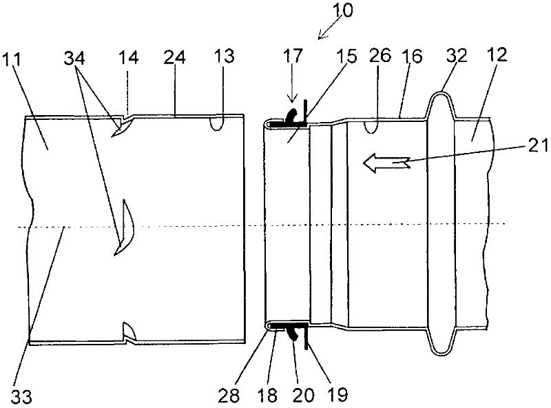
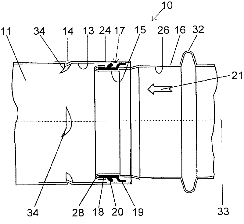
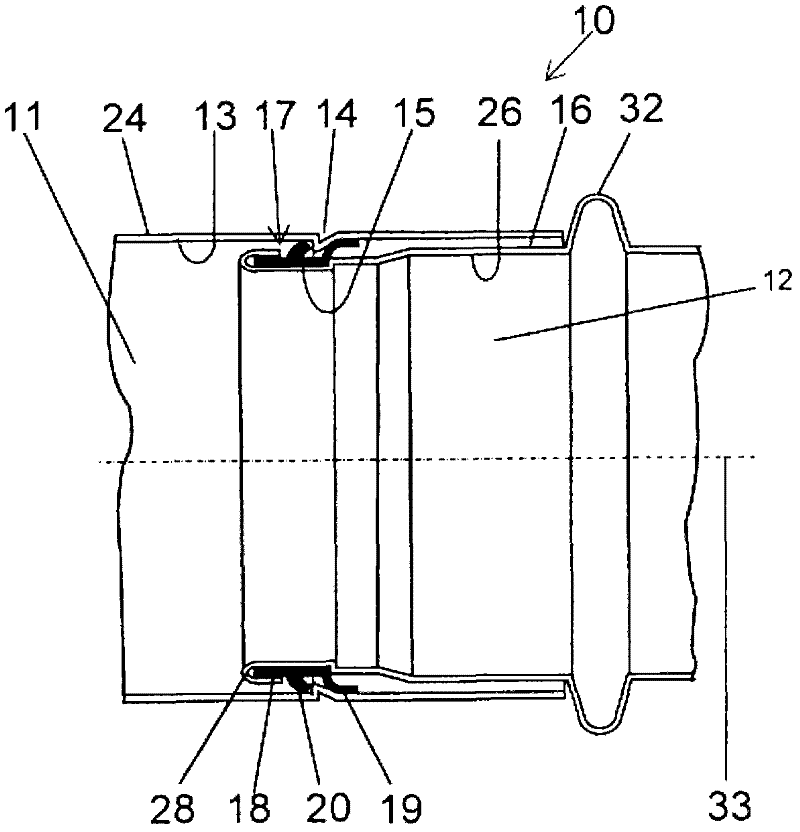
[0034] Figure 1 to Figure 5 A longitudinal sectional view of the pipe connection structure 10 in the first embodiment of the present invention is shown. The pipe connection structure 10 includes a first pipe piece 11 and a second pipe piece 12 , wherein a locking mechanism 14 is provided on the pipe inner wall 13 of the first pipe piece 11 . Therefore, a plurality of locking mechanisms 14 can likewise be provided on the inner tube wall 13 . The number of locking mechanisms 14 is mainly determined by the diameters of the first and second pipes 11 , 12 . Preferably, said locking mechanism 14 is arranged axisymmetrically with respect to the longitudinal axis 33 of the first or second tubular member 11 , 12 . The end 15 of the second pipe 12 is inserted into the first pipe 11 . Thus, the outer diameter of the second pipe 12 at the end 15 is smaller than the inner diameter of the first pipe. Of course, it is also an option that the outer diameter of the second pipe member 12 i...


PUM


Abstract

The invention relates to a pipe connection arrangement for connecting pipe elements, comprising a first pipe element having at least one locking means arranged on the pipe inner wall, a second pipe element having an end section, wherein the second pipe element can be inserted into the first pipe at least in the region of the end section, a separate sealing means arranged at least in a part region of the end section to be completely surrounding its pipe outer wall, equipped to seal a connection between the first pipe element and the second pipe element, characterized in that the sealing means is equipped and designed at the same time as an arresting means to arrest the first and second pipe elements with each other while engaging the sealing means with the locking means.

Description

technical field [0001] The present invention relates to a pipe connection structure, comprising a first pipe part provided with at least one locking mechanism on the inner wall of the pipe, a second pipe part with an end, wherein at least the end part of the second pipe part is inserted into the first pipe part, and A separate sealing mechanism for sealing the connection between the first pipe member and the second pipe member is provided on at least a portion of the end portion and completely surrounds the outer wall of the pipe. Background technique [0002] The structure described above is particularly applicable to ventilation ducts. In order to connect ventilation ducts of different diameters, it is known to insert the end of one duct into the end of another duct. For pipes with the same diameter, in most cases the diameter of one pipe end is reduced by the corresponding dimension of the wall thickness of the other pipe in order to achieve insertion of the pipes into o...

Claims


Application Information

Patent Timeline
Patent Type & Authority Applications(China)
IPC IPC(8): F16L21/025
CPCF24F13/0209F16L21/08F16L21/035F16L17/025
Inventor 奥斯卡·莫卡文
Owner 奥斯卡·莫卡文
Why Eureka
Try Eureka