Antenna and terminal

An antenna and terminal technology, which is applied to antennas, antenna arrays, antenna components, etc., can solve the problems of small effective space, poor isolation, and poor correlation coefficient in the antenna area, so as to reduce the difficulty of development and improve the isolation and correlation coefficient. , the effect of good complementarity of the pattern

Inactive Publication Date: 2012-07-11
HUAWEI DEVICE CO LTD
View PDF4 Cites 19 Cited by
  • Summary
  • Abstract
  • Description
  • Claims
  • Application Information

AI Technical Summary

Problems solved by technology

[0002] With the development of wireless communication technology, wireless fidelity (abbreviated as WIFI in English, spelled as Wireless Fidelity in English) technology has been widely used, but the data card is generally relatively small, and the antenna area of ​​the data card with wireless fidelity function The effective space is relatively small, which makes the isolation and correlation coefficient between the input and output antennas poor. However, wireless communication has higher and higher requirements for the performance of the antenna. It is hoped that wireless protection can be achieved in a limited space. The true frequency band, and the indicators are better, especially the isolation and correlation coefficient, which increases the data card broadband multiple input multiple output (MIMO in English, spelled in English as Multiple-Input Multiple-Out-put,) antenna design difficulty
[0003] In the prior art, in order to improve the isolation and correlation coefficient of the MIMO antenna in the WiFi frequency band of the data card, the MIMO antenna in the WiFi frequency band of the data card is usually composed of two distant monopole antennas , try to increase the distance between the two monopole antennas in a limited space to improve the isolation and correlation coefficient between the antennas. This solution increases the difficulty of antenna development

Method used


Image

  • Antenna and terminal
  • Antenna and terminal
  • Antenna and terminal

Examples


Embodiment Construction

[0013] The following will clearly and completely describe the technical solutions in the embodiments of the present invention with reference to the accompanying drawings in the embodiments of the present invention. Obviously, the described embodiments are only some, not all, embodiments of the present invention. Based on the embodiments of the present invention, all other embodiments obtained by persons of ordinary skill in the art without creative efforts fall within the protection scope of the present invention.

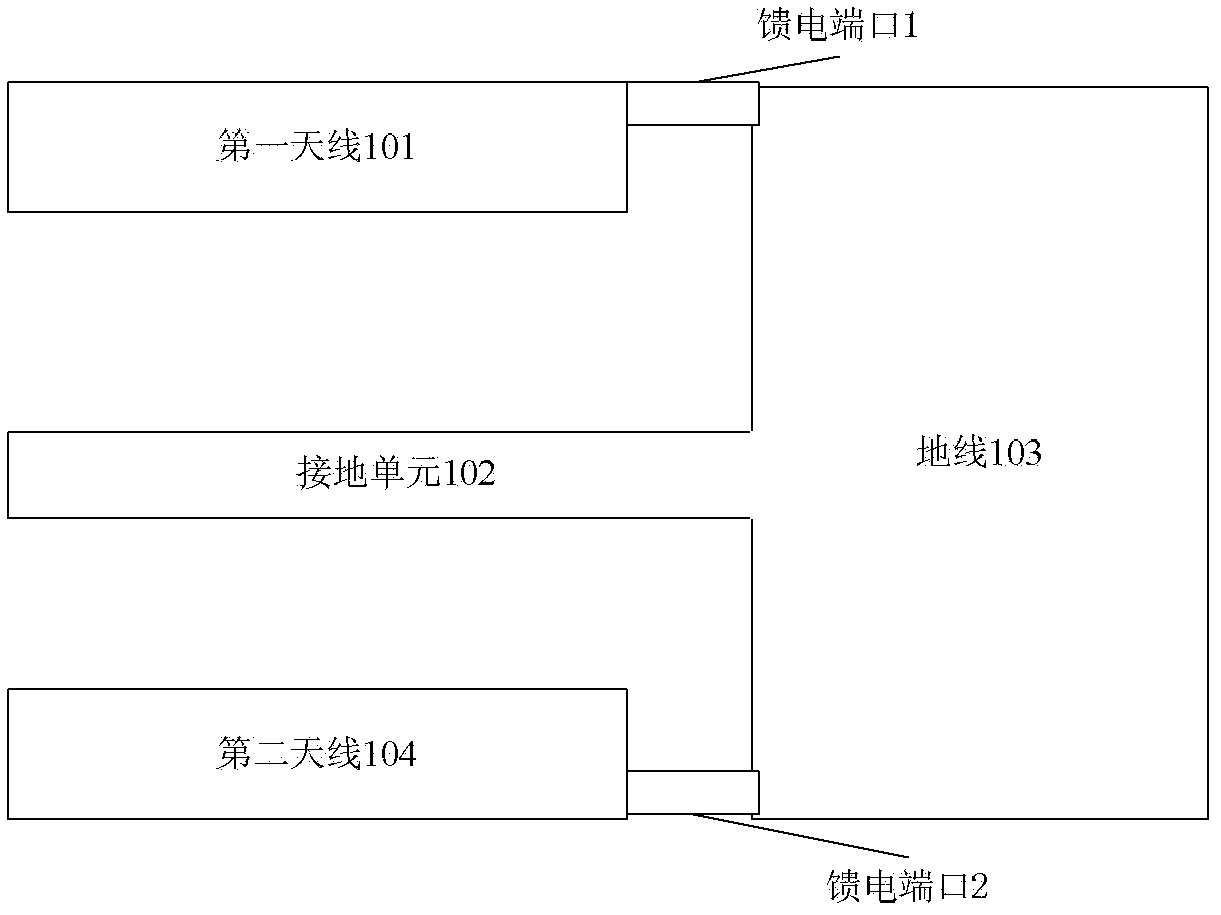
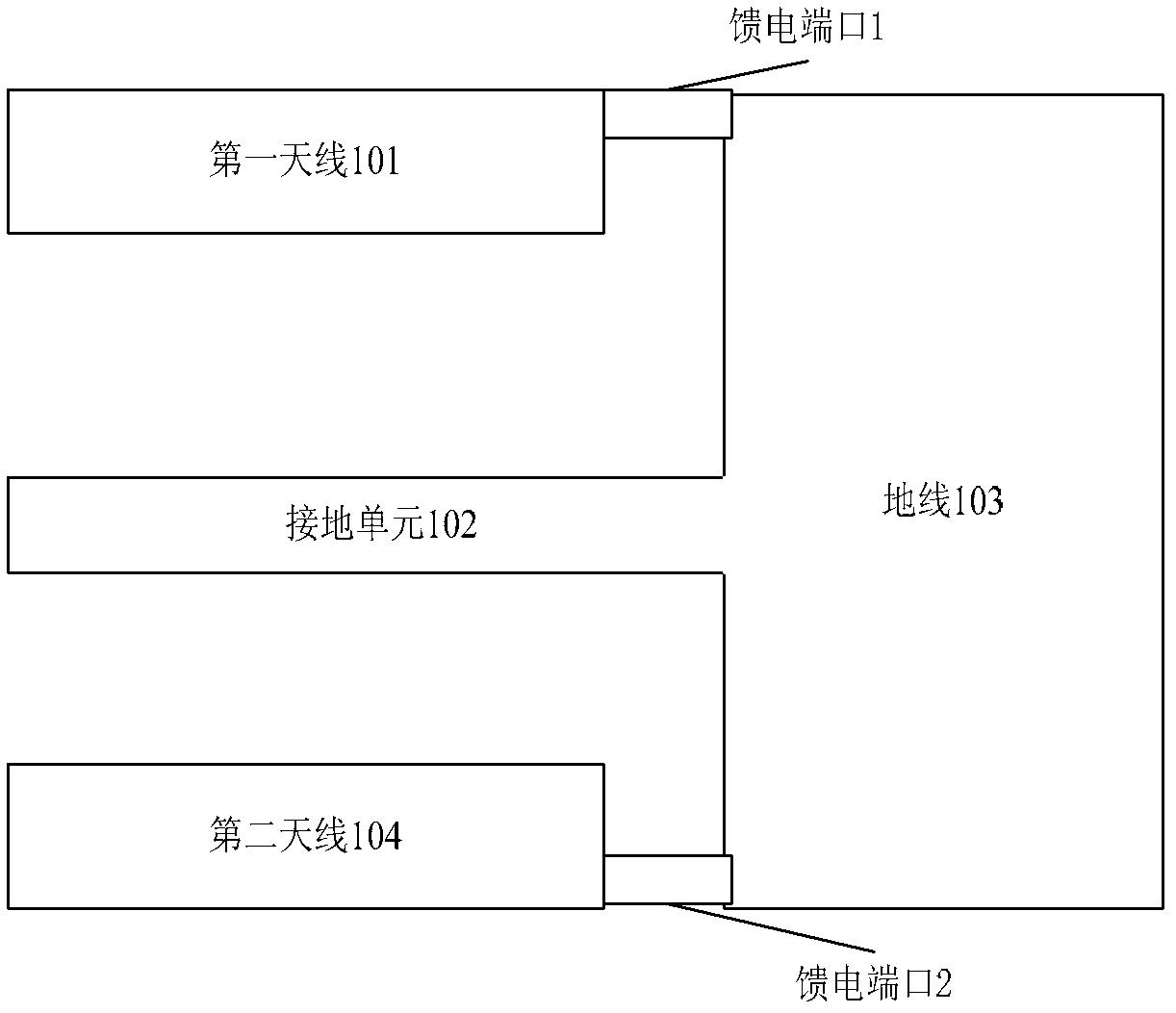
[0014] see figure 1 , the embodiment of the present invention provides an antenna, including: a first antenna 101 , a ground unit 102 , a ground wire 103 and a second antenna 104 .

[0015] Wherein, the distance between the first antenna 101 and the second antenna 104 is within a preset range, the grounding unit 102 is located between the first antenna 101 and the second antenna 104, and the grounding unit 102 is not in contact with the first antenna 101 and the s...


PUM


Abstract

Provided in the embodiments of the present invention and relating to the field of communications are an antenna and a terminal, the antenna comprising: a first antenna, a grounding unit, a ground wire and a second antenna; the grounding unit is positioned between the first and the second antennae but does not contact either antenna; one end of the grounding unit is connected to the ground wire; the grounding unit is symmetrical in structure and the axis of symmetry thereof is perpendicular to the ground wire; the first and the second antennae are connected respectively to the ground wire by corresponding electrical feed ports. The present invention utilizes two antennae in a small space and provides between said two antennae a symmetrical grounding structure; the isolation of each antenna from the other provides excellent complementarity of the two antenna patterns, enhances the degree of isolation and the correlation coefficient of the two antennae, and reduces the difficulty of antenna development.

Description

technical field [0001] The present invention relates to the field of communication technology, in particular to an antenna and a terminal. Background technique [0002] With the development of wireless communication technology, wireless fidelity (abbreviated as WIFI in English, spelled as Wireless Fidelity in English) technology has been widely used, but the data card is generally relatively small, and the antenna area of ​​the data card with wireless fidelity function The effective space is relatively small, which makes the isolation and correlation coefficient between the input and output antennas poor. However, wireless communication has higher and higher requirements for the performance of the antenna. It is hoped that wireless protection can be achieved in a limited space. The true frequency band, and the indicators are better, especially the isolation and correlation coefficient, which increases the data card broadband multiple input multiple output (MIMO in English, s...

Claims


Application Information

Patent Timeline
Patent Type & Authority Applications(China)
IPC IPC(8): H01Q1/48H01Q21/00H01Q5/10
CPCH01Q1/521
Inventor 范毅兰尧孙树辉
Owner HUAWEI DEVICE CO LTD
Why Eureka
Try Eureka