Unlock instant, AI-driven research and patent intelligence for your innovation.

Adjusting mechanism for slide track of drawer

A technology of adjusting mechanism and drawer, which is applied in the direction of drawers, furniture parts, household appliances, etc., can solve the problems of inappropriate adjustment of the left and right positions of the drawers, large locking force, and inability to meet the needs of consumers, and achieves simple design and reasonable structure. , the effect of low production cost

Inactive Publication Date: 2012-07-18
伍志勇
View PDF6 Cites 10 Cited by
  • Summary
  • Abstract
  • Description
  • Claims
  • Application Information

AI Technical Summary

Problems solved by technology

It is said that the lever-type lock bar is set on the connecting seat to fasten and connect with the drawer slide rail. Its locking force is large, and it has the characteristics of quick assembly and low production cost, but it is not suitable for adjusting the left and right positions of the drawer. Can not meet the increasing demand of consumers

Method used


Image

  • Adjusting mechanism for slide track of drawer
  • Adjusting mechanism for slide track of drawer
  • Adjusting mechanism for slide track of drawer

Examples


no. 1 example

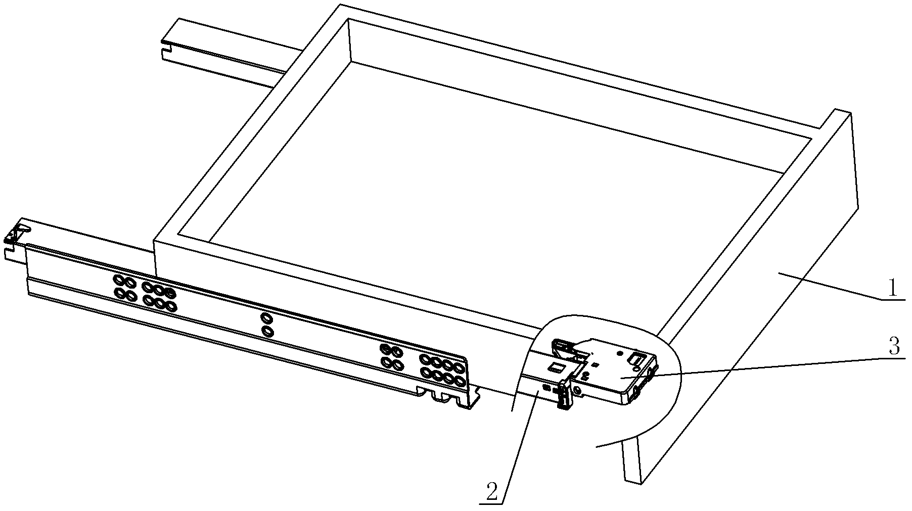
[0039] see Figure 1-Figure 17 , the adjustment mechanism of the drawer slide rail, including the pull-out rail 2 and the connecting seat 3 arranged on the lower side of the drawer 1, the connecting seat 3 is detachably connected with the pull-out rail 2 through an elastic lock rod (no label in the figure), and the connecting seat 3 is fixed on the lower side of the drawer 1, and a left and right adjustment mechanism that can adjust the left and right positions of the drawer 1 is provided between the connecting seat 3 and the pull-out rail 2.

[0040] The left and right adjusting mechanism includes an adjusting screw rod 31 and a drive rack 32 connected thereto, and the drive rack 32 is connected between the coupling base 3 and the pull-out rail 2 . An intermediate gear 33 is also transmission-connected between the adjusting screw rod 31 and the driving rack 32 .

[0041] In this embodiment, the left and right adjustment mechanism is arranged on the coupling seat 3 . Adjusti...

no. 2 example

[0046] see Figure 18-Figure 21 , the main difference between the adjustment mechanism of the drawer slide rail and the first embodiment is that the adjustment screw 31 is placed vertically, correspondingly, the bayonet 3.1 is not required on the coupling seat 3, and the end of the adjustment screw 31 is provided with a rotating shaft (No number in the figure) is connected to the connection seat 3 in rotation, and the rotating shafts at both ends of the intermediate gear 33 are respectively connected to the connection seat 3 and the shield 5 in rotation. habit, and further expand its scope of application. Other unmentioned parts are the same as the first embodiment and will not be repeated.


PUM


Abstract

An adjusting mechanism for a slide track of a drawer comprises a drawable track and connecting seat which are disposed on the lower side of a drawer. The connecting seat is detachably connected with the drawable track, and a left and right adjusting mechanism capable of adjusting the left and right position of the drawer is disposed between the connecting seat and the drawable track. The left and right adjusting mechanism comprises an adjusting screw stem and a driving rack which is connected onto the adjusting screw stem in a transmission manner, and the driving rack is connected between the connecting seat and the drawable track. An intermediate gear is further connected between the adjusting screw stem and the driving rack in a transmission manner. The left and right adjusting mechanism is disposed on the connecting seat or the drawable track. The driving rack is driven to slide left and right by means of turning the adjusting screw stem of the left and right adjusting mechanism, so that the left and right position between the drawer and the drawable track is adjusted, and the drawer and a cabinet are assembled more neatly and attractively. In addition, the adjusting mechanism has the advantages of simple design, reasonable structure, low manufacturing cost and quick assembly.

Description

technical field [0001] The invention relates to a drawer, in particular to an adjustment mechanism for a drawer slide rail. Background technique [0002] Chinese Patent Document No. CN102326978A disclosed on January 25, 2012 a lock adjustment mechanism for drawer slide rails, including a coupling seat arranged on the bottom surface of the drawer, and a lock bar is rotatably connected to the coupling seat, and one end of the lock bar is set A lock tongue is buckled and connected with the slide rail, and a handle extends from the other end, and the lock tongue is separated from the slide rail by pressing the handle. The lock tongue is provided with an inclined guide surface corresponding to the slide rail, and the rear of the guide surface is a stepped locking part, which is fastened and connected with the lock hole provided on the slide rail, and the number of steps of the stepped locking part is More than two levels. The locking rod is arranged on the pillar of the couplin...

Claims


Application Information

Patent Timeline
Patent Type & Authority Applications(China)
IPC IPC(8): A47B88/04
Inventor 伍志勇
Owner 伍志勇
Features
  • R&D
  • Intellectual Property
  • Life Sciences
  • Materials
  • Tech Scout
  • Unparalleled Data Quality
  • Higher Quality Content
  • 60% Fewer Hallucinations
Learn More