
Shell body and manufacturing method thereof

A manufacturing method and shell technology, which are applied in chemical instruments and methods, metal casings, decorative arts, etc., can solve the problems of insufficient color, complexity, and difficulty in maintaining decorative appearance of the vacuum coating layer.

Inactive Publication Date: 2012-07-18
HONG FU JIN PRECISION IND (SHENZHEN) CO LTD +1
View PDF3 Cites 2 Cited by
  • Summary
  • Abstract
  • Description
  • Claims
  • Application Information

AI Technical Summary

Problems solved by technology

However, plastic shells and painted shells cannot present a good metallic texture
On the other hand, because the vacuum coating technology itself is relatively complicated and difficult to precisely control, the color of the metal vacuum coating layer formed on the surface of the shell in the prior art is limited. Compared with baking paint, anodizing and other processes, the color of the vacuum coating layer is not enough. rich, limiting its competitiveness in the field of decorative coatings
At the same time, the wear resistance of the color film layer sputtered by PVD is generally poor, so that the shell will be discolored and peeled off during use, and it is difficult to maintain a long-term good decorative appearance

Method used

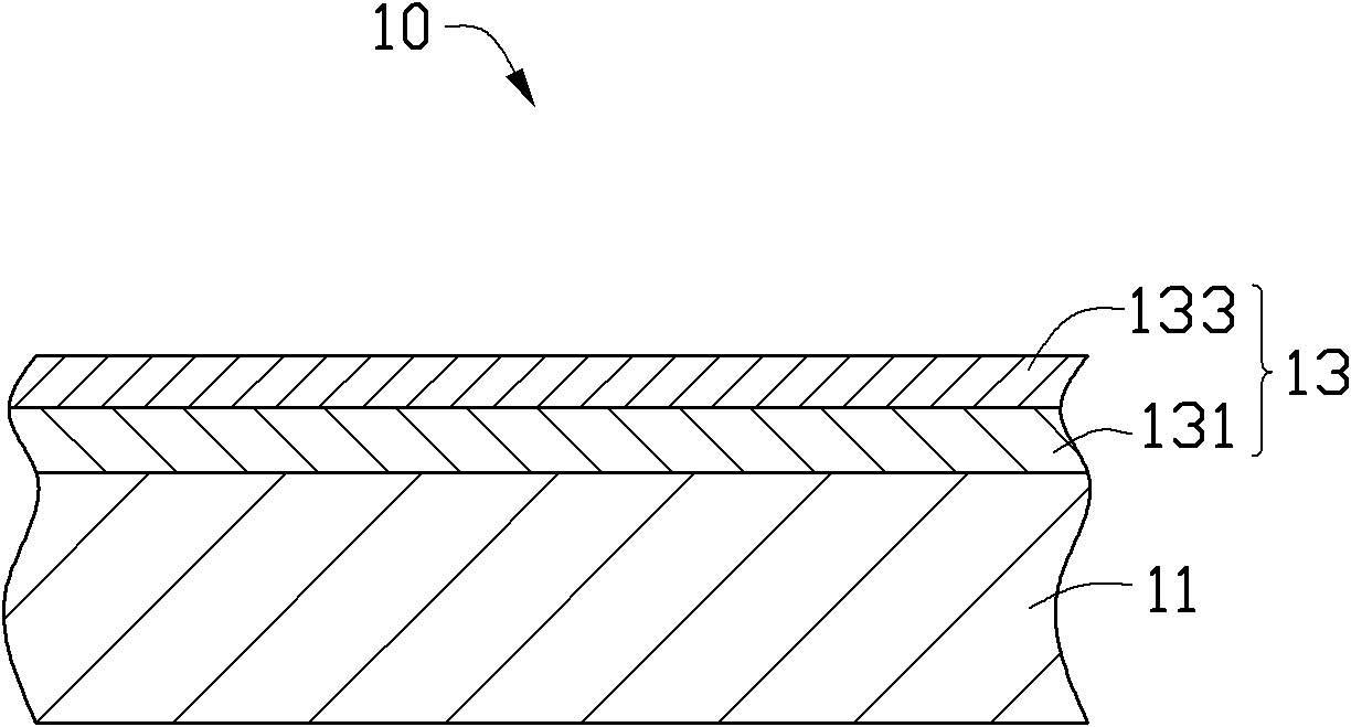
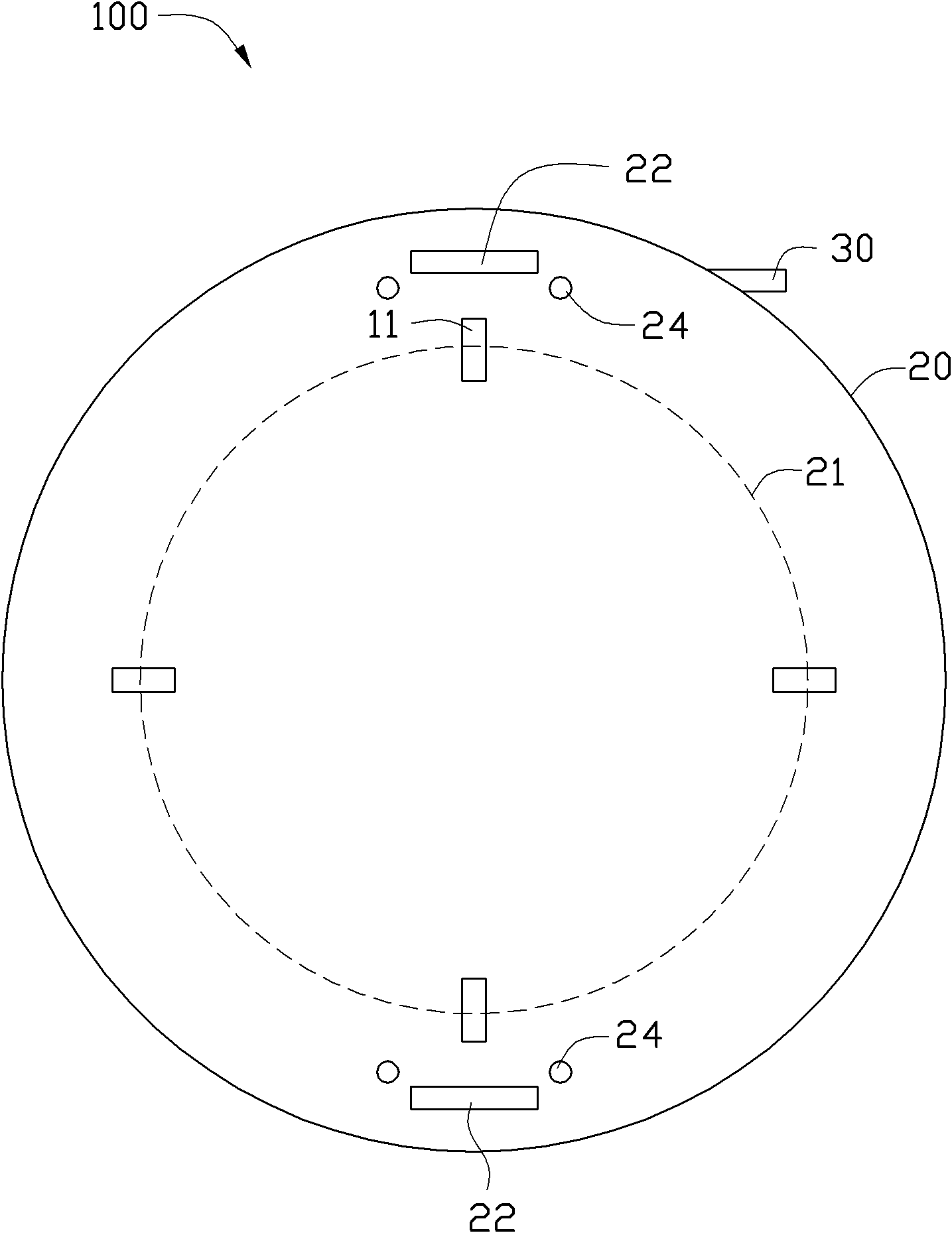
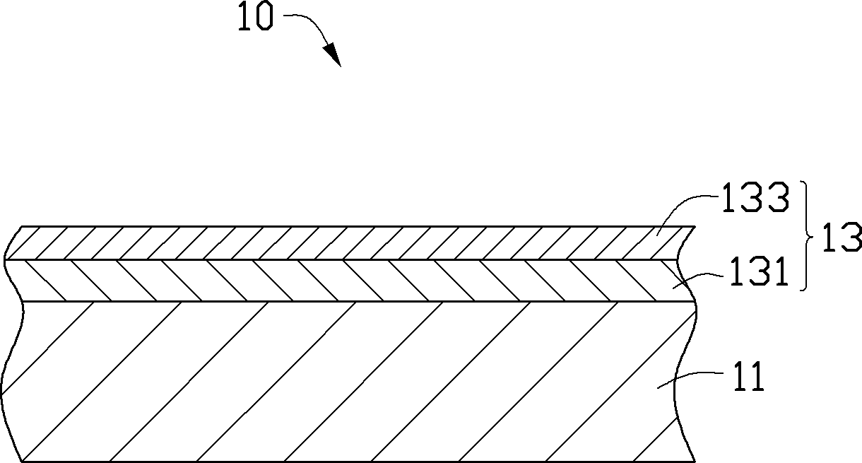

Image

  • Shell body and manufacturing method thereof
  • Shell body and manufacturing method thereof
  • Shell body and manufacturing method thereof

Examples


Embodiment 1

[0039] Plasma cleaning: the argon gas flow rate is 300 sccm, the bias voltage of the aluminum or aluminum alloy substrate 11 is -300V, and the plasma cleaning time is 10 minutes;

[0040] Sputtering the aluminum layer 131: argon gas 150 sccm is introduced, the power of the aluminum target 22 is set to 10 kw, the bias voltage of the aluminum or aluminum alloy substrate 11 is set to 200 V, and the deposition is 90 min;

[0041] Sputtering aluminum oxide layer 133: the process parameters are: use argon as the working gas with a flow rate of 150 sccm, use oxygen as the reaction gas, set the flow rate of oxygen to 50 sccm, and apply a bias voltage of -200V on the aluminum or aluminum alloy substrate , the deposition time is 60min.

Embodiment 2

[0043] Plasma cleaning: the argon gas flow rate is 300 sccm, the bias voltage of the aluminum or aluminum alloy substrate 11 is -300V, and the plasma cleaning time is 10 minutes;

[0044] Sputtering the aluminum layer 131: argon gas 150 sccm is introduced, the power of the aluminum target 22 is set to 10 kw, the bias voltage of the aluminum or aluminum alloy substrate 11 is set to -200 V, and the deposition is 90 min;

[0045] Sputtering aluminum oxide layer 133: using argon as the working gas with a flow rate of 150 sccm, using oxygen as the reaction gas, setting the flow rate of oxygen to 100 sccm, applying a bias voltage of -200V on the aluminum or aluminum alloy substrate, and the deposition time is 60 minutes .

Embodiment 3

[0047] Plasma cleaning: the argon gas flow rate is 300 sccm, the bias voltage of the aluminum or aluminum alloy substrate 11 is -300V, and the plasma cleaning time is 10 minutes;

[0048]Sputtering the aluminum layer 131: argon gas of 150 sccm is introduced, the power of the aluminum target 22 is set to 10 kw, the bias voltage of the aluminum or aluminum alloy substrate 11 is set to -200 V, and the deposition time is 90 min;

[0049] Sputtering aluminum oxide layer 133: using argon as the working gas with a flow rate of 150 sccm, using oxygen as the reaction gas, setting the flow rate of oxygen to 75 sccm respectively, applying a bias voltage of 200V on the aluminum or aluminum alloy substrate, and the deposition time is 60 minutes .

[0050] The manufacturing method of the casing 10 is to sequentially form a decorative color layer 13 on the aluminum or aluminum alloy substrate by magnetron sputtering. The color layer 13 includes an aluminum layer 131 and an aluminum oxide la...


PUM

PropertyMeasurementUnit
thicknessaaaaaaaaaa
thicknessaaaaaaaaaa

Abstract

The invention relates to a shell body comprising aluminum or an aluminum alloy matrix and a color layer which is formed on the surface of the aluminum or the aluminum alloy matrix; the color layer comprises an aluminum layer and an alumina layer which are sequentially formed on the surface of the aluminum or the aluminum alloy matrix; the coordinate L* of a chroma area on the color layer in a CIE LAB natural color system is between 75 and 100, the coordinate a* of the chroma area is between -1 and 1, and the coordinate b* of the chroma area is between -1 and 1. The invention also provides a manufacturing method of the shell body, which comprises the following steps that: the aluminum or the aluminum alloy matrix is provided; the color layer is sputtered on the aluminum or aluminum alloy matrix through magnetic control; the color layer comprises the aluminum layer and the alumina layer which are sequentially formed on the surface of the aluminum or the aluminum alloy matrix; and the shell body has good wear resistance and a decorative appearance.

Description

technical field [0001] The invention relates to a casing and a manufacturing method thereof. Background technique [0002] With the continuous advancement of technology, various electronic devices such as mobile phones, personal digital assistants (PDA, Personal Digital Assistant), and computers are also developing rapidly, and their functions are becoming more and more abundant. In order to make the casing of the electronic device rich in color, traditionally, colored plastics can be used to form the colored plastic casing, or a color layer is formed on the surface of the casing of the electronic device by spraying paint. However, plastic shells and painted shells cannot present a good metallic texture. On the other hand, because the vacuum coating technology itself is relatively complicated and difficult to precisely control, the color of the metal vacuum coating layer formed on the surface of the shell in the prior art is limited. Compared with baking paint, anodizing an...

Claims


Application Information

Patent Timeline
Patent Type & Authority Applications(China)
IPC IPC(8): H05K5/04B32B9/04B32B15/20B44C5/04
CPCB32B9/04H05K5/04B44C5/04B32B15/20C23C14/0015C23C14/021C23C14/081C23C14/165Y10T428/12611
Inventor 张新倍陈文荣蒋焕梧陈正士万自成
Owner HONG FU JIN PRECISION IND (SHENZHEN) CO LTD
Learn More