
Flange connector for vacuum insulation low-temperature pipelines

A pipeline flange and vacuum insulation technology, which is applied in the direction of flange connection, pipeline protection through heat insulation, pipe/pipe joint/pipe fitting, etc., to achieve reliable sealing effect

Inactive Publication Date: 2012-07-25
AEROSUN CORP
View PDF9 Cites 10 Cited by
  • Summary
  • Abstract
  • Description
  • Claims
  • Application Information

AI Technical Summary

Problems solved by technology

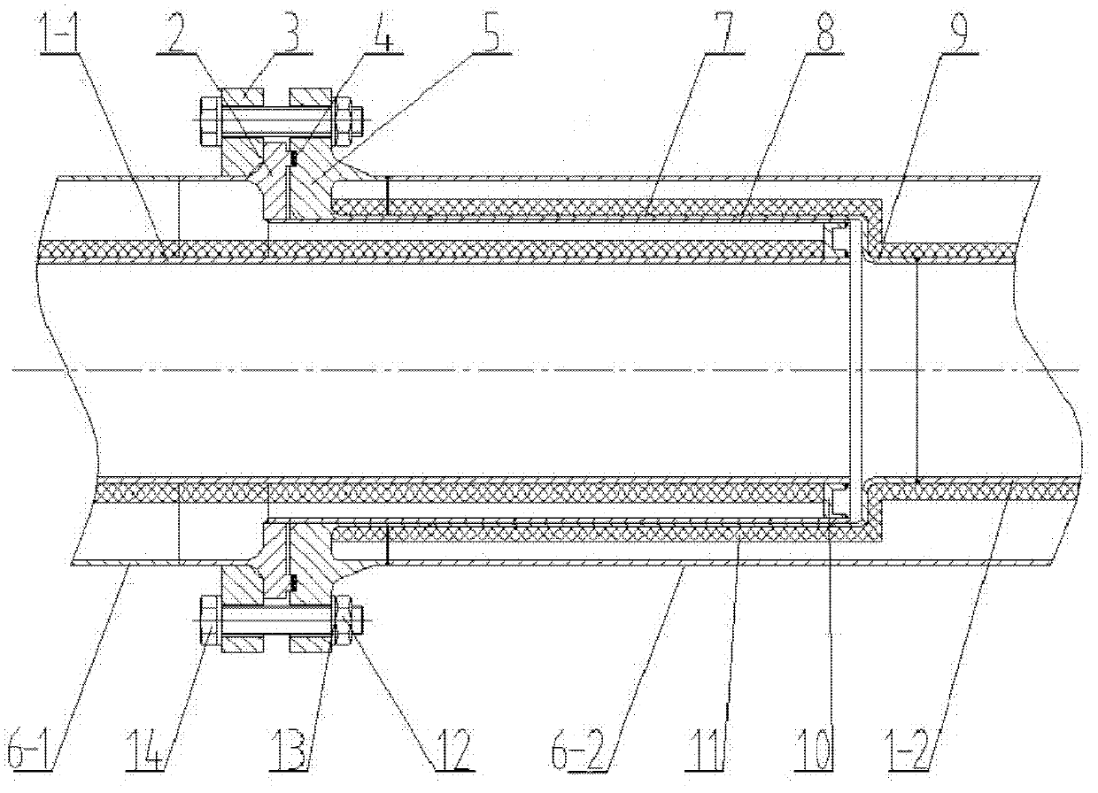
[0006] The technical problem to be solved by the present invention is: aiming at the problems existing in the above-mentioned prior art, through structural improvement, a vacuum insulated low-temperature pipeline flange connection joint that can avoid cold shrinkage deformation of the seal is proposed, so as to ensure its sealing performance

Method used


Image

  • Flange connector for vacuum insulation low-temperature pipelines
  • Flange connector for vacuum insulation low-temperature pipelines

Examples


Embodiment

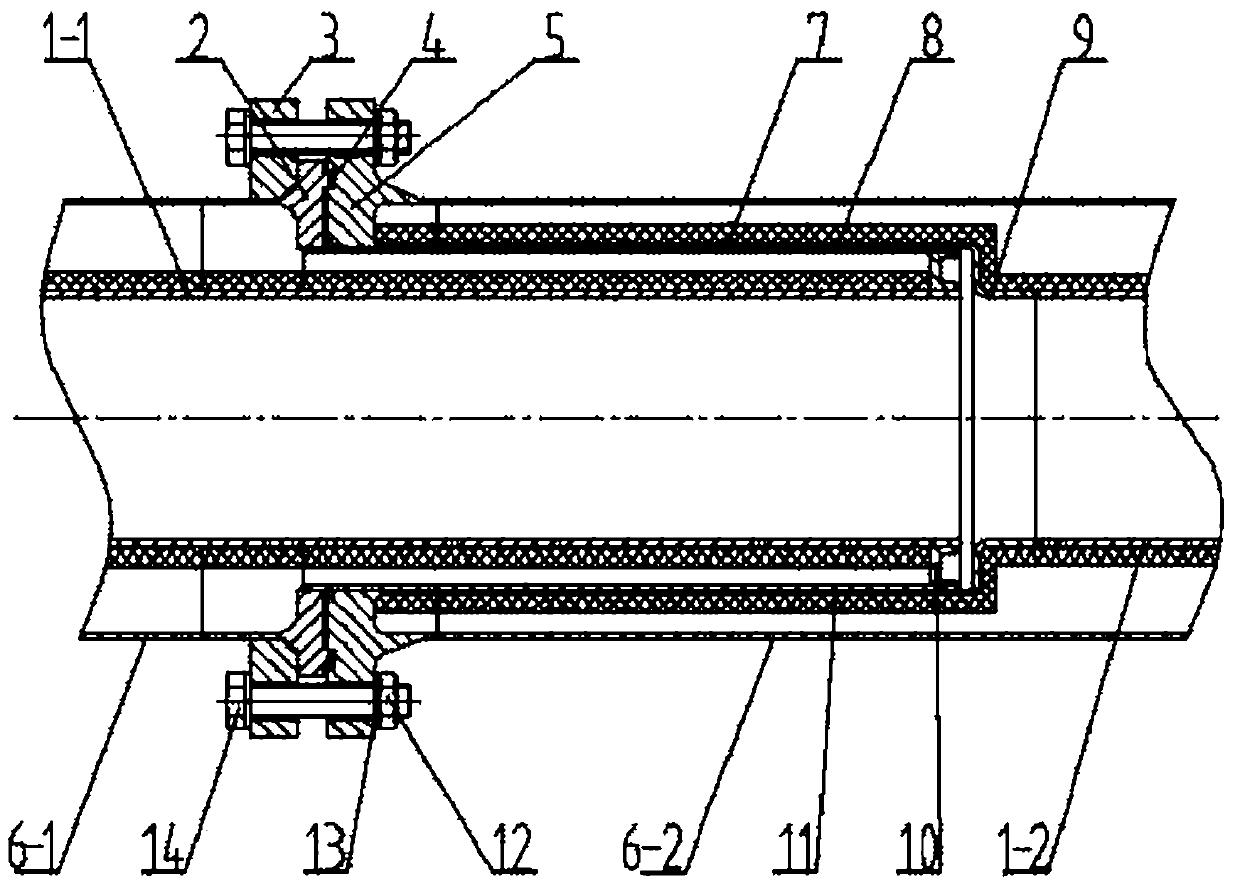
[0013] This embodiment is a vacuum insulation cryogenic pipeline flange connection joint, and its specific structure is as follows figure 1 As shown, the first pipeline and the second pipeline that are connected to each other are respectively composed of inner tubes 1-1, 1-2 coated with heat insulating material 11 and outer tubes 1-1, 1-2 that are sleeved outside to form a vacuum interlayer. The tubes 6-1 and 6-2 are composed; the end surface of the inner tube 1-1 of the first pipeline exceeds the port of the outer tube 6-1 of the first pipeline, and the end surface of the outer tube 6-2 of the second pipeline exceeds the inner tube 1-1 of the second pipeline 2 ports.

[0014] The end of the first pipeline outer tube 6-1 on the left has a joint plate 2 extending radially inward and outward, the inner hole of the joint plate 2 extends axially outward to form a sleeve-shaped flange heat bridge 8, and the end of the flange heat bridge 8 It is welded with the port of the inner pi...


PUM


Abstract

The invention relates to a flange connector for vacuum insulation low-temperature pipelines, belonging to the technical field of pipeline connection. A first pipeline and a second pipeline of the connector are respectively composed of an inner pipe and an outer pipe, the end tip of the outer pipe of the first pipeline is provided with a connector plate, and an inner hole of the connector plate axially extends outwards to form a convex edge heat bridge; the end tip of the outer pipe of the second pipe is provided with a flange plate, and an inner hole of the flange plate axially extends outwards to form a concave edge heat bridge; during the assembly, the connector plate and the flange plate are butt-jointed, sealed and fixed in a way that a convex ring is clamped into a groove in which a sealing ring is embedded; meanwhile, the convex edge heat bridge is inserted into the concave edge heat bridge and keeps an air gap with the concave edge heat bridge. The flange connector disclosed by the invention adopts a reasonable structure, and ingeniously uses separation sealing of the air gap to replace an inner sealing part, so that the sealing performance is guaranteed.

Description

technical field [0001] The invention relates to a low-temperature pipeline flange connection joint, in particular to a vacuum heat-insulated low-temperature pipeline flange connection joint, which belongs to the technical field of fluid delivery pipelines. Background technique [0002] In the fields of low-temperature cryogenic liquefaction and cryogenic fluid storage and transportation, pipelines that continuously transport cryogenic liquids for a long time mostly use vacuum multi-layer insulation cryogenic pipelines. Restricted by installation conditions and requirements for use and maintenance, cryogenic pipelines with vacuum multi-layer insulation are often composed of multiple pipe units with independent vacuum chambers combined through flange joints. [0003] The search found that the Chinese utility model patent No. 200720186333.X disclosed a flange connection structure of a multi-layer vacuum insulation tube with low heat leakage rate, and the Chinese utility model p...

Claims


Application Information

Patent Timeline
Patent Type & Authority Applications(China)
IPC IPC(8): F16L23/16F16L59/07
CPCF16L59/141F16L59/184
Inventor 刘灿荣王芳衡彪
Owner AEROSUN CORP
Learn More