Accurate magnetic compass in mobile electronic device

一种移动装置、主机装置的技术,应用在罗盘、测量装置、磁场的大小/方向等方向

Inactive Publication Date: 2012-07-25
QUALCOMM INC
View PDF5 Cites 13 Cited by
  • Summary
  • Abstract
  • Description
  • Claims
  • Application Information

AI Technical Summary

Problems solved by technology

However, the accuracy of a sensor implementation depends not only on the accuracy of the sensor itself, but also on various external forces that can operate to degrade the accuracy of the sensor

Method used


Image

  • Accurate magnetic compass in mobile electronic device
  • Accurate magnetic compass in mobile electronic device
  • Accurate magnetic compass in mobile electronic device

Examples


Embodiment Construction

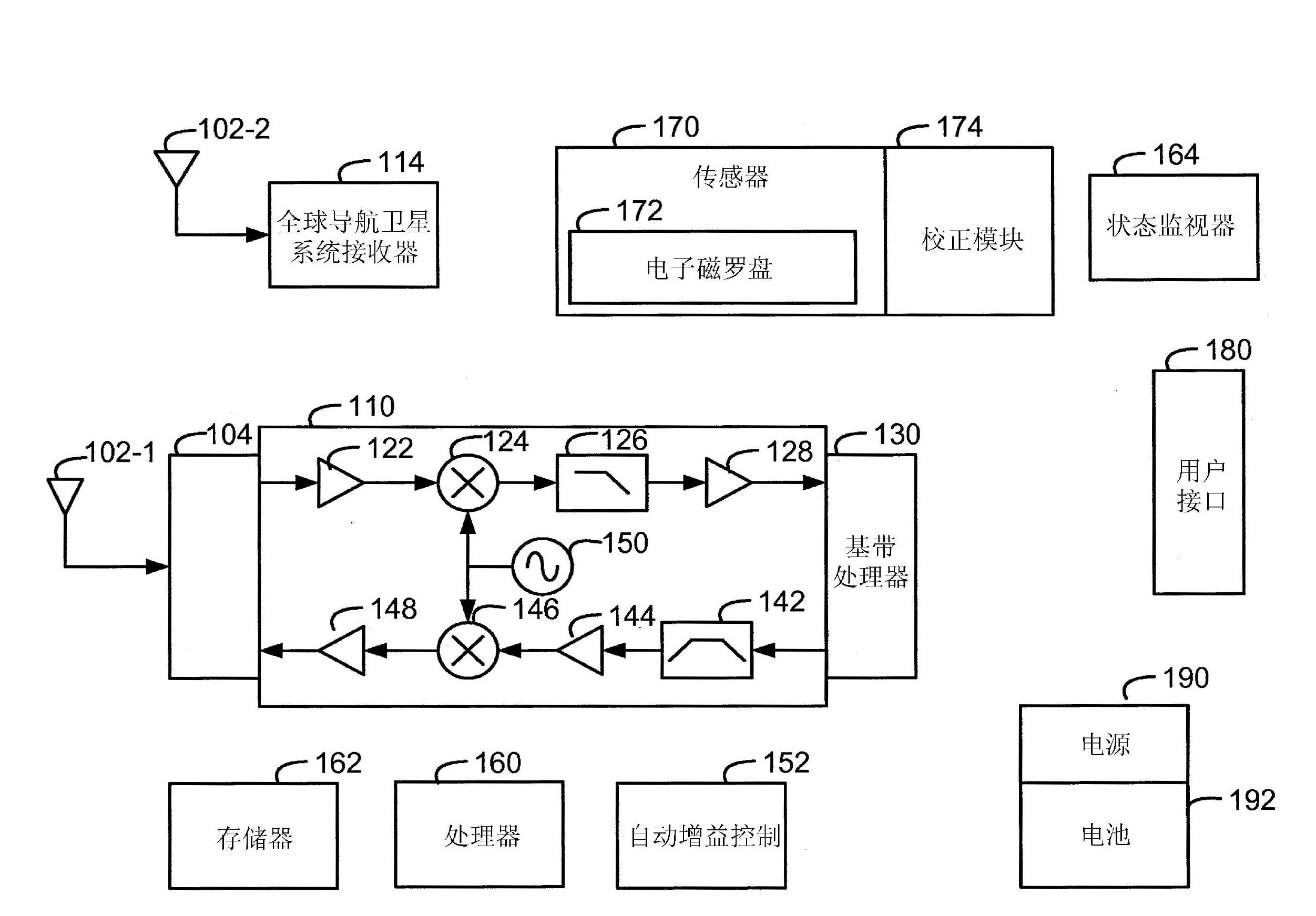
[0015] Described herein are methods and apparatus for maintaining the accuracy of sensor output when the sensor is implemented in a dynamically changing sensor environment. Dynamic calibration and correction methods and apparatus to maintain sensor accuracy over a wide range of device operating modes are described herein.

[0016] An example of a sensor with reduced cost, size and power consumption is a 2-axis or 3-axis magnetometer that enables it to be added to a host device. A magnetometer is a type of sensor that can be used to measure the direction and / or strength of a magnetic field in the vicinity of the sensor. An example of a magnetometer is a solid-state Hall effect sensor that can be used to generate a voltage proportional to an applied magnetic field and to sense the polarity of the magnetic field. Another example of a magnetometer is a fluxgate magnetometer.

[0017] Based on the magnetometer output, and sometimes other sensor data like accelerometer output, the...


PUM


Abstract

Methods and apparatus are described herein for calibration and correction of non-constant sensor errors, and in particular non-constant compass errors, that are based in part on changing software and hardware modes of a host device. The non-constant errors induced in the sensor by each mode and combination of modes is determined in a calibration that may be determined during pre-production testing of one or more host devices. The calibration results can be incorporated into software and / or hardware of the host device. During normal operation, a sensor correction can be applied to sensor measurements based in part on the active mode or combination of modes.

Description

technical field [0001] The invention relates to the field of electronic sensors. In particular, the invention relates to the field of improving the accuracy of electronic sensors. Background technique [0002] Electronic and electromechanical devices are increasingly implementing electronic sensors. Devices rely on information provided by sensors to support autonomous monitoring and related functional features. For example, a device may implement electronic sensors to monitor acceleration, magnetic heading, light levels, and the like. [0003] As the cost of incorporating such sensors has decreased, the number and types of devices implementing the sensors have increased. Additionally, as the quality of the sensor improves, the ability of the host device to monitor or otherwise respond to small changes in the sensor output improves. However, the accuracy of a sensor implementation depends not only on the accuracy of the sensor itself, but also on various external forces t...

Claims


Application Information

Patent Timeline
Patent Type & Authority Applications(China)
IPC IPC(8): G01C17/38
CPCG01C17/38G01C17/28G01R33/02
Inventor 维克托·库里克克里斯托福·布鲁纳
Owner QUALCOMM INC
Why Eureka
Try Eureka