Metal deactivator discharge device

A metal passivator and material technology, applied in the direction of feeding devices, chemical instruments and methods, chemical/physical processes, etc., can solve the problems of discontinuous production and increased production costs, and achieve strong continuous working ability, reduce waste, well-designed effects

Inactive Publication Date: 2012-08-01
宜兴汉光高新石化有限公司
View PDF4 Cites 0 Cited by
  • Summary
  • Abstract
  • Description
  • Claims
  • Application Information

AI Technical Summary

Problems solved by technology

However, this will cause discontinuous production, and the reactor needs to be reheated when the next synthesis is carried out, which greatly increases the production cost

Method used


Image

  • Metal deactivator discharge device
  • Metal deactivator discharge device

Examples


Embodiment Construction

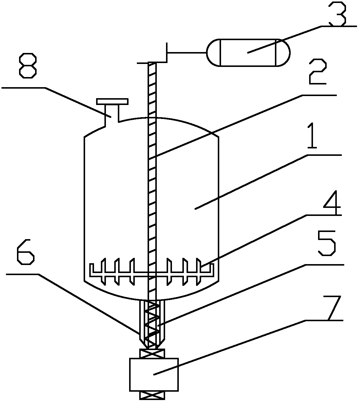
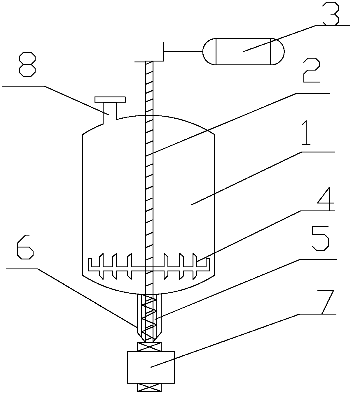
[0009] As shown in the figure, a metal passivating agent discharge device provided by the present invention includes a reactor 1, a rotating shaft 2 runs through the reactor 1, and the outer side of the rotating shaft 2 is connected with a motor 3, and the rotating shaft 2 is connected to the reactor 1. A scraper 4 is connected inside, and a discharge stirring cage 5 is arranged on the outside of the rotating shaft 2 below the reaction kettle 1, and a rubber ring is set on the outside of the joint between the reaction kettle 1 and the discharge stirring cage 5, and a stirring cage is set on the outside of the excretion stirring cage 5. A storage box 7 is provided directly below the cage casing 6 and the excretion stirring cage 5, and a material inlet 8 is opened on the top of the reaction kettle 1 .


PUM


Abstract

The invention discloses a metal deactivator discharge device, which comprises a reactor. A rotating shaft penetrates through the reactor, the outer side of the rotating shaft is connected with a motor, the rotating shaft is further connected with a scraper blade in the reactor, a discharge stirring cage is disposed outside the rotating shaft below the reactor, a storage box is disposed right below the discharge stirring cage, and a material inlet is arranged at the top of the reactor. The metal deactivator discharge device is reasonable in design, high in continuous work ability and convenient in repair, and reduces waste of energy.

Description

technical field [0001] The invention belongs to the field of chemical industry, and in particular relates to a metal passivating agent discharge device. Background technique [0002] Metal deactivators are usually synthesized in a reactor and taken out after the temperature drops. However, this will cause discontinuous production, and the reactor needs to be reheated when the next synthesis is carried out, which greatly increases the production cost. Contents of the invention [0003] Purpose of the invention: the purpose of the present invention is to provide a metal passivator discharge device for the deficiencies in the prior art. [0004] Technical solution: In order to achieve the above object, the present invention is specifically accomplished in this way: a metal passivating agent discharge device includes a reactor, a rotating shaft runs through the reactor, and the outer side of the rotating shaft is connected with a motor, and the rotating shaft is connected to ...

Claims


Application Information

Patent Timeline
Patent Type & Authority Applications(China)
IPC IPC(8): B01J4/00B01J19/18
Inventor 顾同新刘公召王喜平宗俊刘梅
Owner 宜兴汉光高新石化有限公司
Why Eureka
Try Eureka