Water-proof sealing cover

A waterproof sealing and sealing sleeve technology, which is applied to bridge parts, bridges, buildings, etc., can solve the problems of poor sealing effect, tension on one side of the rubber, and reduced rubber use effect, so as to achieve good waterproof effect, good sealing effect, Good sealing and waterproof effect

Inactive Publication Date: 2012-08-01
LIUZHOU OVM MASCH CO LTD
View PDF9 Cites 10 Cited by
  • Summary
  • Abstract
  • Description
  • Claims
  • Application Information

AI Technical Summary

Problems solved by technology

At present, in the process of design and use of cables, there is a way to use a rigid waterproof cover to fasten it on the pre-embedded nozzle to prevent rainwater from entering. It is usually only used at the pre-embedded pipe at the beam end; The pipe is completely fixed, so the seal is incomplete or the seal is damaged due to the vibration of the cable body; in addition, because the cable body is not concentric with the embedded pipe diameter, it will cause installation difficulties or unsatisfactory waterproof effect; moreover, the processing cost is relatively high
The patent publication number is: CN 201660849 U's utility model patent discloses a "rubber waterproof device for bridge cables", which can be used for the pre-embedded pipes at the beam end and the pre-embedded pipes at the tower end of the cables, although it can partially overcome the The shortcomings of the rigid waterproof cover, but there are still the following shortcomings: 1. The transition between the cone and the cylinder cannot be completely sealed; 2. When the cable body and the embedded pipe diameter are not concentric, it is easy to make the rubber Tension on one side reduces the use effect of rubber; 3. The sealing effect of clamps at both ends of the size is not good, and it is easy to damage the rubber

Method used


Image

  • Water-proof sealing cover
  • Water-proof sealing cover
  • Water-proof sealing cover

Examples


Embodiment 1

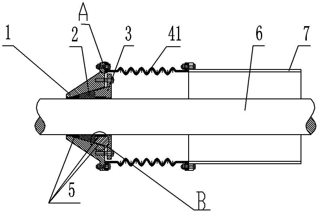
[0040] A cylindrical integral waterproof sealing cover, such as Picture 1-1 As shown, the waterproof sealing cover includes a fixed sleeve 1 of a separate structure, a sealing rubber 2, a compression ring 3 and a cylindrical integral corrugated sealing sleeve 41;

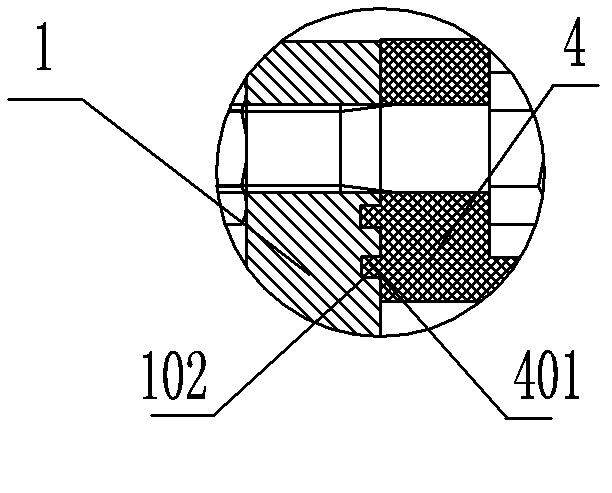
[0041] The fixed sleeve 1 is a truncated cone with an inner tapered hole (see Figure 2-1 to Figure 2-3 ), the sealing rubber 2 is a truncated cone with an inner hole (see Figure 3-1~Figure 3-2 , the taper of the inner tapered hole of the fixed sleeve 1 cooperates with the outer tapered surface of the frustum-shaped sealing rubber 2;

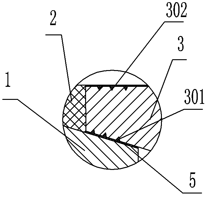
[0042] The compression ring 3 is composed of a cone and a flange as a whole (see Figure 4-1~Figure 4-2 ), there are 1 to 5 sealing grooves 301, 302 ( Figure 1-3 There are 3 sealing grooves respectively), the outer tapered surface of the cone is matched with the inner tapered surface of the fixed sleeve; bolt holes 303 are evenly distributed on the flange for the connection of th...

Embodiment 2

[0049] A cylindrical split type waterproof sealing cover, such as Figure 6 As shown, the basic structure of the waterproof sealing cover is the same as the first embodiment, the difference is that: the fixed sleeve 1, the sealing rubber 2, the compression ring 3, and the corrugated sealing sleeve are all two-half structures, and the corrugated sealing The sleeve 42 is a cylindrical bellows with a two-half structure, and side wings 402 are provided on both sides of each half of the corrugated sealing sleeve 42 body, and screw holes 403 for connecting the two halves of the body are provided on the side wings; Stainless steel plates 8 are provided on both sides and end faces of the body of the half corrugated sealing sleeve 42, and the two cylindrical split type corrugated sealing sleeves 42 are either straight or concave-convex at the two halves of the butt joint (see Figure 5-1~Figure 5-2 , Figure 6 ), Figure 5-1~Figure 5-2 Only planar butt joints are drawn in .

[0050]...

Embodiment 3

[0052] A kind of cone integral waterproof sealing cover, such as Figure 7 As shown, the basic structure of the waterproof sealing cover is the same as that of the first embodiment, the difference is that the corrugated sealing cover of the waterproof sealing cover is a cone-shaped integral structure, and the cone tube is pre-installed according to the size of the anchor head during construction. The integral corrugated sealing sleeve 43 is set on the cable body and fixed at the position to be installed; after the tensioning of the cable is completed, the position to be installed is determined, and the fixing sleeve 1 is installed first, then the sealing rubber is installed, and the sealing medium is filled, and then Install the compression ring so that the fixed sleeve is completely fixed on the cable body, clean up the excess sealing medium that is squeezed out, fill the gaps that still exist with sealing medium, and finally install the corrugated sealing sleeve 43 (see Fig...


PUM


Abstract

The invention discloses a water-proof sealing cover for a stay cable or a lifting rod. The water-proof sealing cover comprises a fixing sleeve, sealing rubber, a compression ring and a corrugated sealing sleeve, wherein the fixing sleeve, the compression ring and the sealing rubber are integral structures or two-half structures; the corrugated sealing sleeve is the integral structure or the two-half structure; during use, the corrugated sealing sleeve with the two-half structure is connected into a whole through a bolt; and the sealing rubber is arranged between the fixing sleeve and the compression ring. Through pre-tensioning force between the fixing sleeve and the compression ring, the sealing rubber is tightly clamped in a cable body, so that the fixing sleeve, the compression ring and the sealing rubber are fixed with the cable body and then are connected with a pre-embedded pipe through the corrugated sealing sleeve. The corrugated sealing sleeve has a plurality of degrees of freedom, the influence of constraint on the cable body is relatively low, and a relatively good sealing effect can be achieved. Furthermore, due to the special structure of the corrugated sealing sleeve, the problem that the water-proof cover cannot be mounted or a using effect cannot be achieved after the water-proof cover is mounted because the cable body is not in the middle of the pre-embedded pipe during practical mounting is solved.

Description

technical field [0001] The invention relates to a waterproof sealing cover suitable for the lower end pre-embedded pipe or the upper end pre-embedded pipe of a stay cable or a suspender. Background technique [0002] The waterproof device is a very important sealing member during the installation and use of the cable. At present, in the process of design and use of cables, there is a way to use a rigid waterproof cover to fasten it on the pre-embedded nozzle to prevent rainwater from entering. It is usually only used at the pre-embedded pipe at the beam end; The pipe is completely fixed, so the seal is incomplete or the seal is damaged due to the vibration of the cable body; in addition, because the cable body is not concentric with the embedded pipe diameter, it will cause difficulty in installation or unsatisfactory waterproof effect; moreover, its processing cost is high. The patent publication number is: CN 201660849 U's utility model patent discloses a "rubber waterpro...

Claims


Application Information

Patent Timeline
Patent Type & Authority Applications(China)
IPC IPC(8): E01D19/16E01D19/08
Inventor 石伟华剑平梁德郡刘界林黄森郑国坤李华萍廖松山叶明坤梁黎霞
Owner LIUZHOU OVM MASCH CO LTD
Why Eureka
Try Eureka