Device and method for detecting cable

A detection device and cable technology, applied in the field of testing, can solve problems such as low efficiency, slow manual detection, and inability to provide a common ground point.

Inactive Publication Date: 2012-08-01
第二炮兵装备研究院中试与检测中心
View PDF6 Cites 7 Cited by
  • Summary
  • Abstract
  • Description
  • Claims
  • Application Information

AI Technical Summary

Problems solved by technology

[0003] The existing intelligent multi-core cable tester uses a processor to control the relay matrix to automatically and quickly realize point-by-point trials, which solves the problem of slow manual detection and low efficiency, and improves the detection speed of multi-core cables. However, it still needs to use External wired or wireless devices provide communication guarantee and provide a basis for switching the relay matrix
[0004] However, in some occasions, it is impossible to provide a common ground point, and it is difficult to provide communication guarantee conditions; therefore, it is impossible to use the existing technology for cable detection

Method used


Image

  • Device and method for detecting cable
  • Device and method for detecting cable
  • Device and method for detecting cable

Examples


Embodiment 1

[0138] Embodiment 1: see attached figure 1 , a cable detection device is characterized in that: it includes: a master device and a slave device respectively connected to the two ends of the cable under test; the master device and the slave device both include: a switch array , a current source 1, a data sending circuit, a data receiving circuit, a matching detector 2, a controller 3 and a man-machine interface 4;

[0139] The switch array includes n identical branches, wherein any branch numbered j is connected to the terminal of the tested cable core numbered j, the wire core numbered j is connected to the switch, and the numbered j is connected to the switch. The circuit selection switches for switching between normally open contacts and normally closed contacts are connected in series; the normally closed contacts of the circuit selection switches in each branch are connected together to form the terminal A of the switch array, and each branch The normally open contacts of...

Embodiment 2

[0149] Embodiment 2: see attached figure 1 , the cable detection device as described in Embodiment 1, is characterized in that: the master device also includes the forward detection circuit and the reverse detection circuit, that is, the structure of the master device and the slave device Similarly, both can be set as a host device or a slave device through the man-machine interface 4 .

Embodiment 3

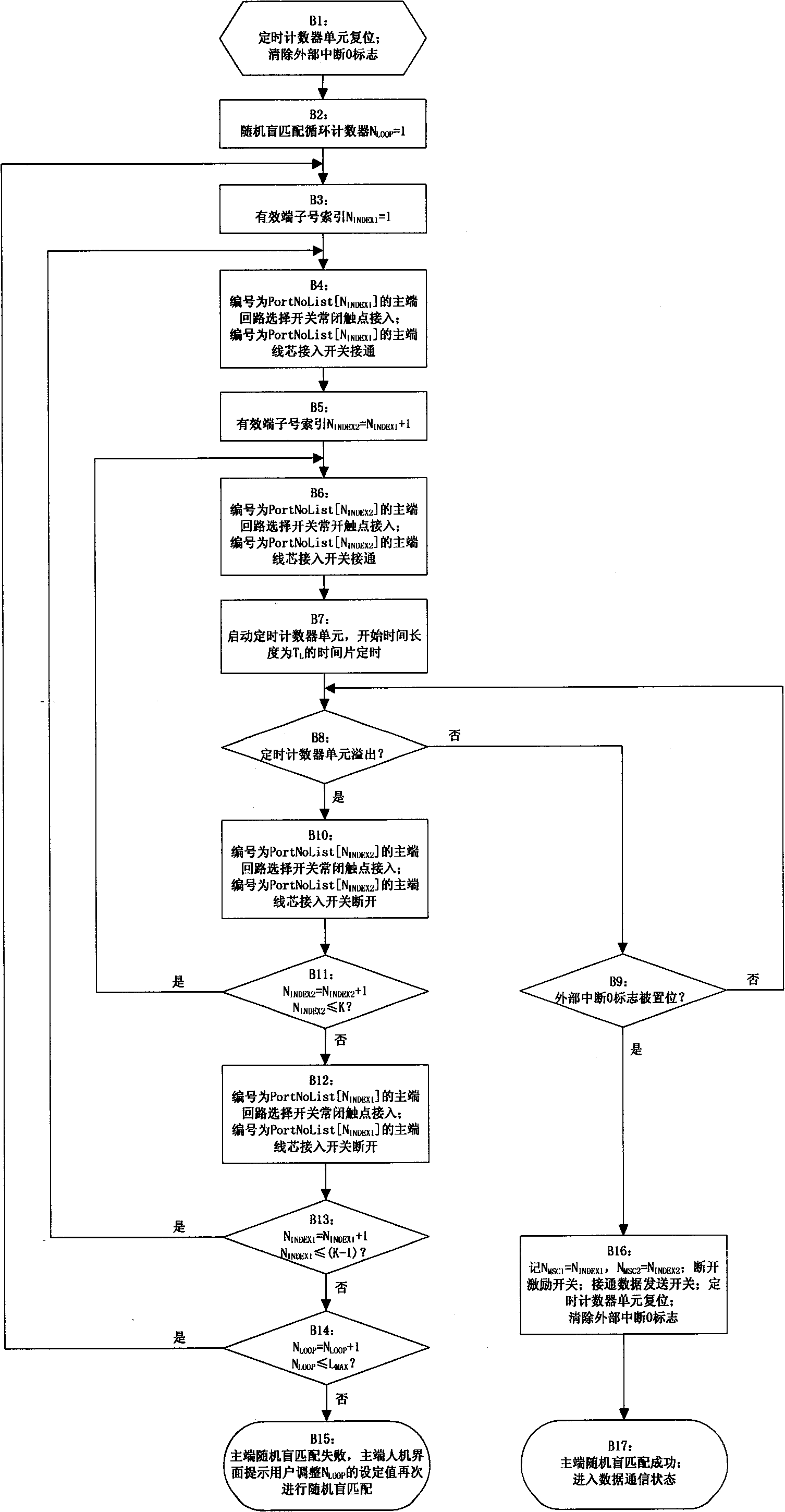
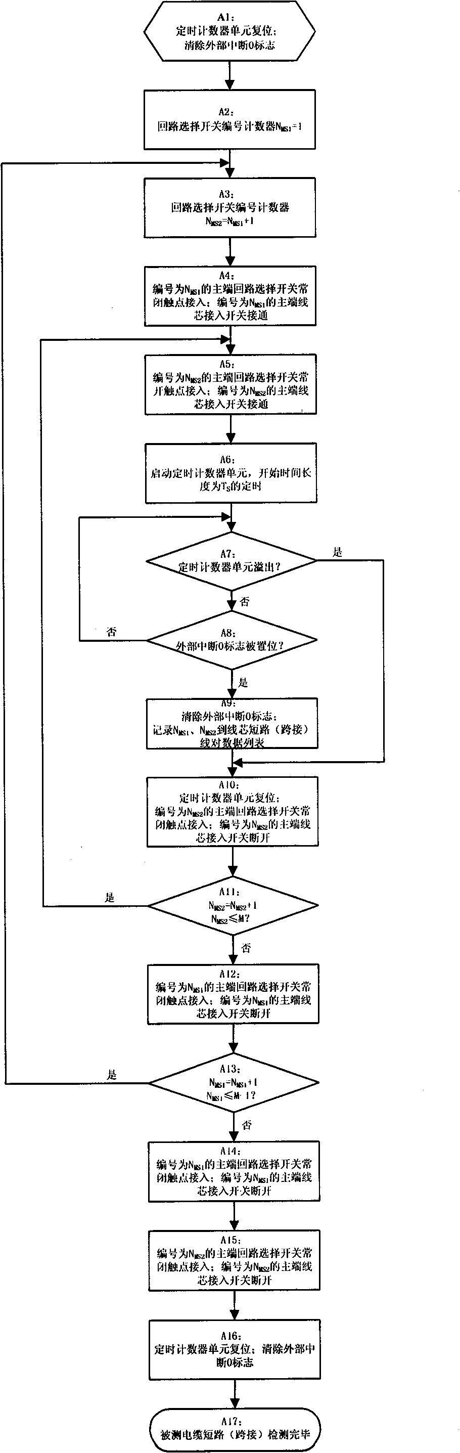
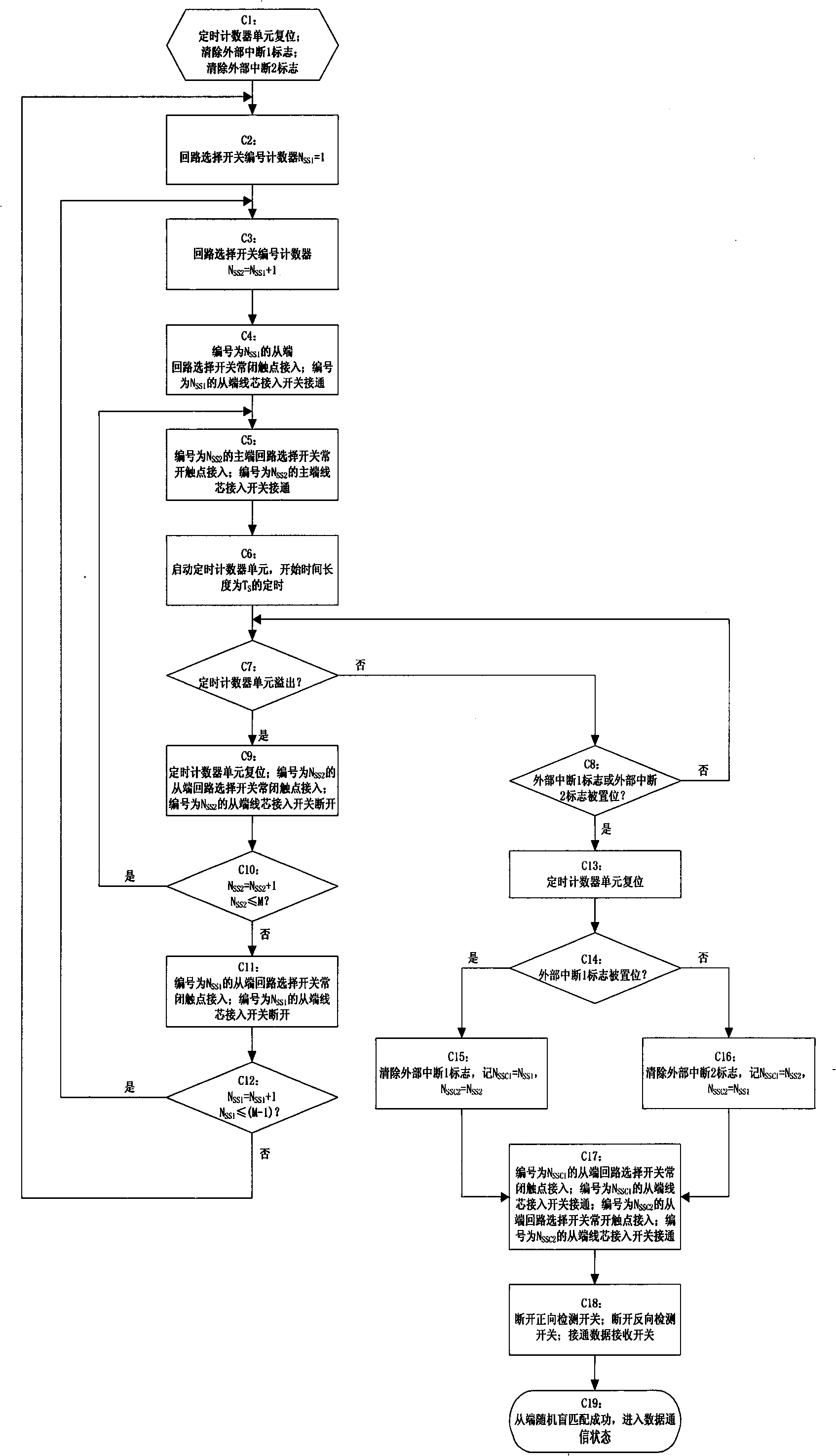
[0150] Embodiment 3: see attached figure 1 , 2 , a kind of cable detection method, it uses the cable detection device as described in embodiment 1 or 2, and comprises the following steps, to complete the short circuit detection between tested cable core wires:

[0151] A0: Let the number of core wires of the cable under test be M, M≤n, give one end of each core wire a number from 1 to M in any order, and connect the cable under test to the slave device corresponding to the number The core is connected to terminals 1~M; after the slave device is powered on, the controller 3 performs device initialization settings: all the circuit selection switches are in the normally closed contact state, and all other switches are in the off state State; input the waiting time value T from the man-machine interface 4 W The slave device enters the idle waiting state;

[0152] At the other end of the cable under test, number each core wire 1~M in any order, and connect to the cable core acce...


PUM


Abstract

The invention belongs to the technical field of testing, and particularly relates to a device and a method for detecting a cable. The device for detecting the cable comprises main end equipment and secondary end equipment which are connected to two ends of a cable to be detected respectively, wherein each of the main end equipment and the secondary end equipment comprises a switch array, a current supply (1), a data transmitting circuit, a data receiving current, a matching detector (2), a controller (3) and a human-machine interface (4); and the secondary end equipment also comprises a forward direction detection circuit and a reverse direction detection circuit. By the device and the method, short circuit, cable sequence and disconnection of the cable can be detected without an external communication support, and common ground points are not needed at two ends of the cable to be detected, so that the device and the method can be used for detecting the cable when the two ends of the cable are at the same position before the arrangement of the cable, and can also be used for detecting the cable when the two ends of the cable are not at the same position during or after the arrangement of the cable, and all the operations can be finished by one operator.

Description

technical field [0001] The invention belongs to the technical field of testing, in particular to a cable testing device and method. Background technique [0002] The detection of multi-core cables usually includes detection of line sequence, open circuit, and short circuit (or jumper, the same below). The distance between the two ends of the cable that has been laid or is being laid may be tens of meters, hundreds of meters or even farther. To detect it, the operators at both ends of the cable need to use the external communication guarantee conditions to try point by point, and the detection speed is slow and the efficiency is low. In order to improve the speed of manual point-by-point detection, the common grounding point at both ends of the cable can be used. If there is no common grounding point at both ends of the cable, a single-core cable with good conduction can be laid to provide the common point. [0003] The existing intelligent multi-core cable tester uses a pro...

Claims


Application Information

Patent Timeline
IPC IPC(8): G01R31/02
Inventor 郑应强朱宝吴晓庆薛继明康宁民
Owner 第二炮兵装备研究院中试与检测中心
Why Eureka
Try Eureka