
Device for clamping and locking inching switch

A jog switch and locking technology, which is applied to the testing of measuring devices, measuring device casings, and mechanical components, can solve problems such as fixed automatic clamping devices for low-voltage switches, and achieve precise positioning and clamping. The degree of automation and the effect of reducing labor intensity

Inactive Publication Date: 2014-12-10
SHANGHAI UNIV OF ENG SCI
View PDF7 Cites 0 Cited by
  • Summary
  • Abstract
  • Description
  • Claims
  • Application Information

AI Technical Summary

Problems solved by technology

[0005] After searching, in the published patents and other reports, no fixed automatic clamping device for low-voltage switches suitable for experiments has been found.

Method used


Image

  • Device for clamping and locking inching switch
  • Device for clamping and locking inching switch
  • Device for clamping and locking inching switch

Examples


Embodiment

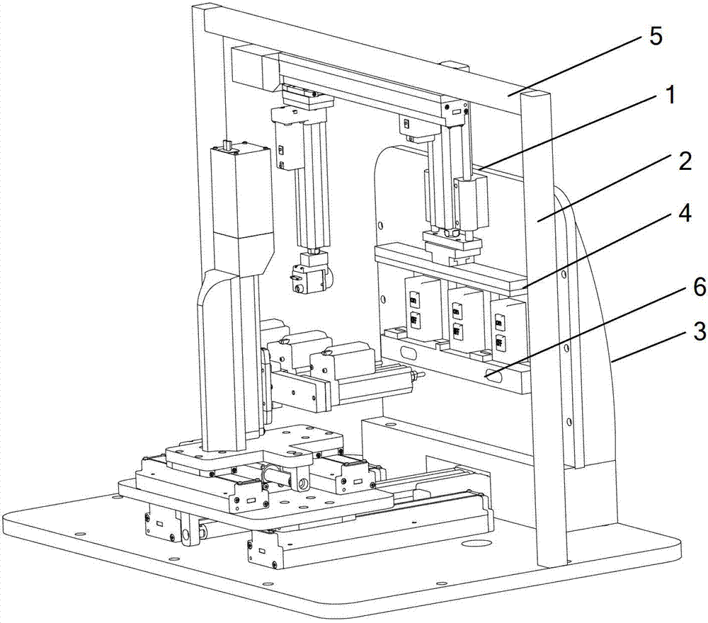
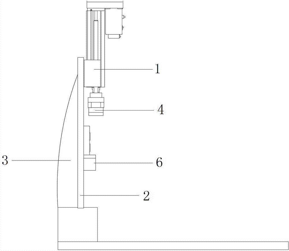
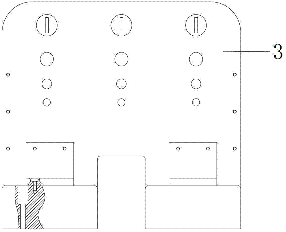
[0024] A device for clamping and locking a point switch, its structure is as follows Figure 1-2 As shown, it includes workbench, bracket 5, electric cylinder 1 and assembly plate 2. The workbench can move up and down in the Z direction. There are guide rails on the workbench, and the bracket 5 is connected to the guide rail of the workbench. The electric cylinder 1 and The vertical posture is connected with the assembly plate 2, in order to provide power for automatic pressing, the lower part of the electric cylinder is equipped with a platen spring buffer mechanism 4, and the assembly plate 2 is provided with a supporting plate 6 for placing the tested sample.

[0025] The lower part of the electric cylinder is provided with a protruding shaft rod, which is threadedly connected with the pressure plate spring buffer mechanism 4. The pressure plate spring buffer mechanism 4 is connected with the shaft of the electric cylinder 1, and the pressure plate spring buffer mechanism 4 ...


PUM


Abstract

The invention relates to a device for clamping and locking an inching switch. The device for clamping and locking the inching switch comprises a workbench, a bracket, an electric cylinder and a mounting plate, wherein the workbench can be moved up and down in the Z direction, a guide rail is arranged on the workbench, the bracket is connected onto the guide rail of the workbench, the electric cylinder for providing power for the realization of an automatic compression effect is vertically connected with the mounting plate, a buffering mechanism of a pressing plate spring is arranged at the lower part of the electric cylinder, and a supporting plate on which a sample to be tested is placed is arranged on the mounting plate. Compared with the prior art, with the adoption of the device for clamping and locking the inching switch disclosed by the invention, the mounting problem of the sample of the inching switch is well solved, the sample is well compressed and buffered, and the surface of the sample is protected from being damaged, so that the automation degree of an experimental facility is greatly increased.

Description

technical field [0001] The invention relates to various experimental devices of jog switches, in particular to a device for clamping and locking a jog switch. Background technique [0002] With the advancement of science and the development of technology, the level of automated production is increasing day by day, and the cost of large-scale experiments using assembly lines is significantly reduced; at the same time, scientific and technological personnel are required to continuously solve many specific technical problems in the process of industrial automated production . [0003] During the life test of the low-voltage electrical switch, the workpiece is automatically positioned and clamped, and related operations are performed. [0004] For example, during the operation life test of the jog switch of low-voltage electrical appliances, the switch needs to be switched on and off. For the on-off life test of the jog switch, the button of the switch is repeatedly pressed unt...

Claims


Application Information

Patent Timeline
Patent Type & Authority Patents(China)
IPC IPC(8): G01M13/00G01R1/04
Inventor 程武山朱明年
Owner SHANGHAI UNIV OF ENG SCI
Learn More