Method and equipment for distributing PDSCH (physical downlink shared channel) power

A technology of power and base station equipment, which is applied in the field of PDSCH power allocation, can solve the problems of not being able to dynamically adjust and better reduce cell downlink interference, and achieve the effects of ensuring fairness, improving downlink performance, and reducing downlink interference

Active Publication Date: 2012-08-15
DATANG MOBILE COMM EQUIP CO LTD
View PDF3 Cites 26 Cited by
  • Summary
  • Abstract
  • Description
  • Claims
  • Application Information

AI Technical Summary

Problems solved by technology

[0012] The existing downlink PDSCH power allocation is that each RE linearly and equally divides the maximum transmit power of the base station equipment, which cannot be dynamically adjusted according to the system performance or user situation changes in actual application scenarios, and cannot better reduce the downlink interference between cells the goal of

Method used


Image

  • Method and equipment for distributing PDSCH (physical downlink shared channel) power
  • Method and equipment for distributing PDSCH (physical downlink shared channel) power
  • Method and equipment for distributing PDSCH (physical downlink shared channel) power

Examples


Embodiment 1

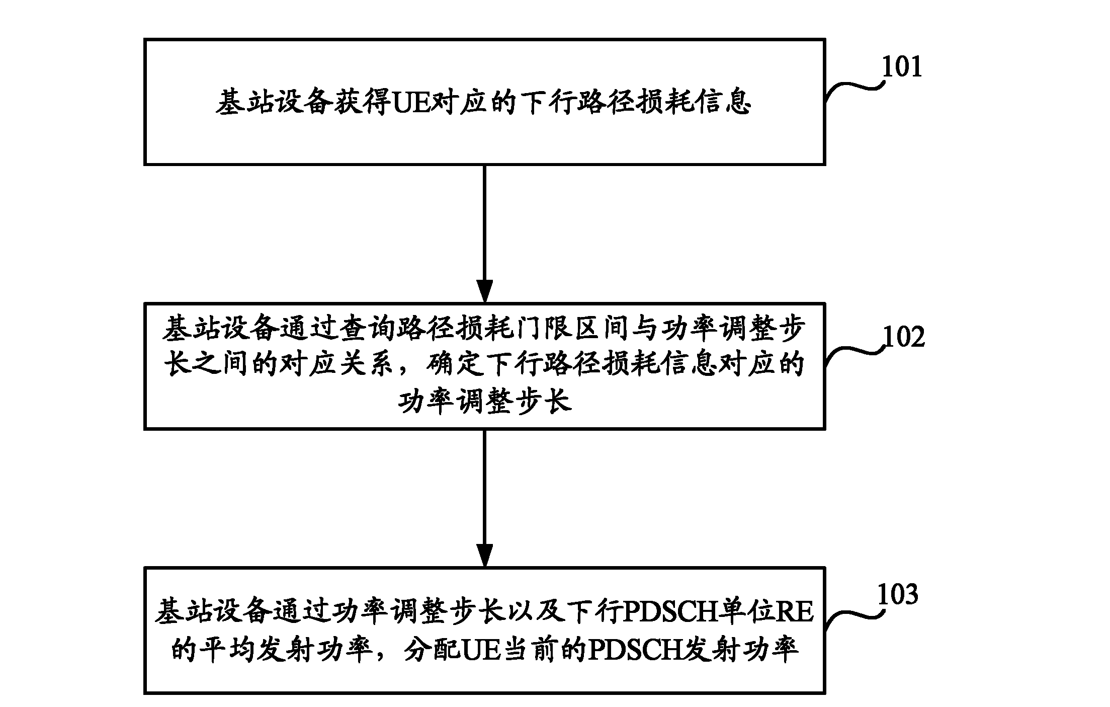
[0028] Embodiment 1 of the present invention provides a PDSCH power allocation method, which dynamically adjusts the PDSCH transmission power based on the downlink path loss (PL) of the UE, thereby reasonably allocating the PDSCH transmission power and effectively reducing the downlink interference between cells, such as figure 1 As shown, the method includes the following steps:

[0029] Step 101, the base station equipment obtains downlink path loss information corresponding to the UE.

[0030] In the embodiment of the present invention, the base station device can periodically obtain the downlink path loss information corresponding to the UE, and the process of obtaining the downlink path loss information corresponding to the UE specifically includes: the base station device calculates the downlink path loss information PL corresponding to the UE through the following formula avr_n :

[0031] PL avr_n = γ·PL n +(1-γ)·PL avr_n-1

[0032] Among them, PL avr_n-1 is the d...

Embodiment 2

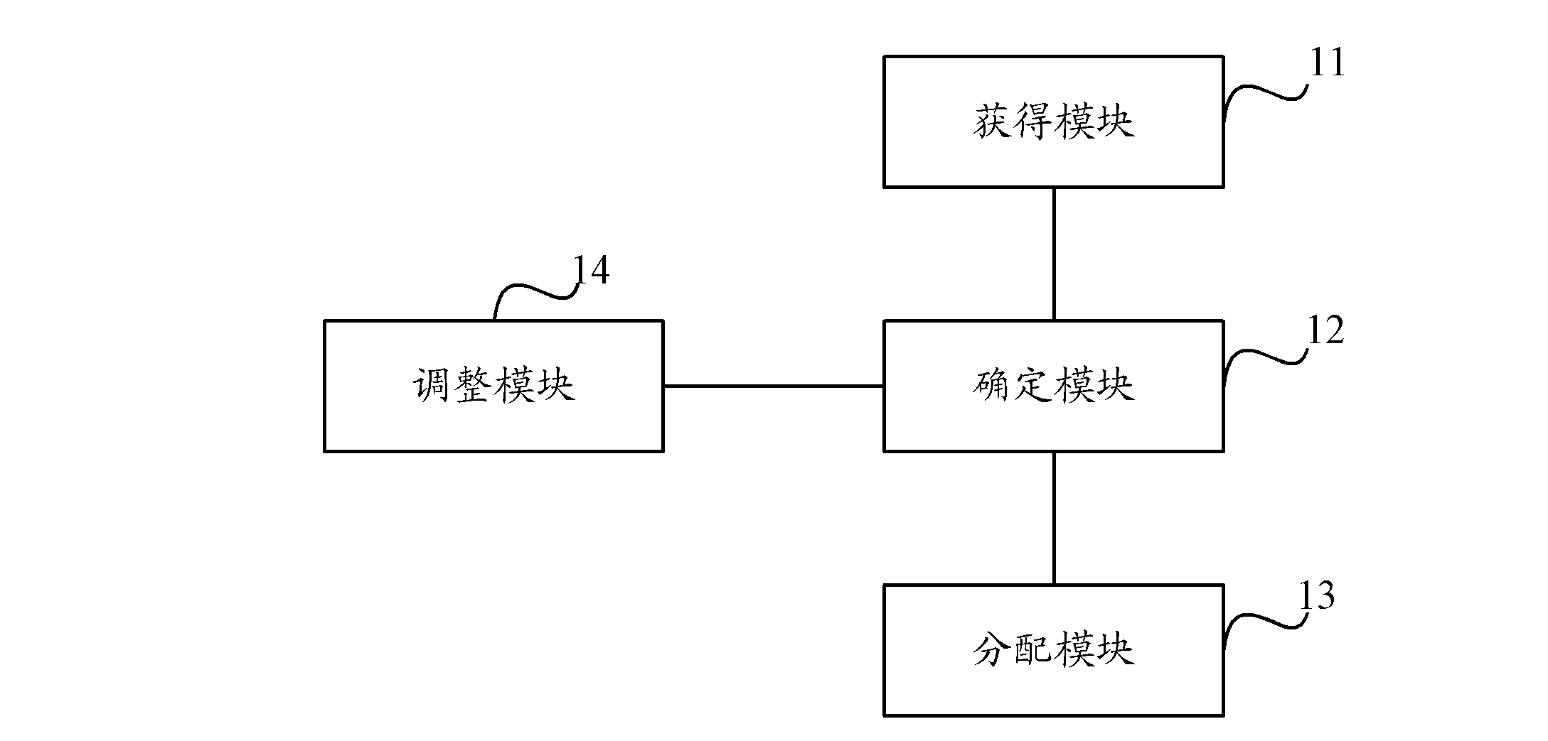
[0070] Based on the same inventive concept as the above method, an embodiment of the present invention also provides a base station device, such as figure 2 As shown, the base station equipment includes:

[0071] An obtaining module 11, configured to obtain downlink path loss information corresponding to the user equipment;

[0072] The determination module 12 is configured to determine the power adjustment step size corresponding to the downlink path loss information by querying the correspondence between the path loss threshold interval and the power adjustment step size;

[0073] The allocation module 13 is configured to allocate the current PDSCH transmission power of the user equipment according to the power adjustment step size and the average transmission power of the downlink PDSCH unit resource element RE.

[0074] The obtaining module 11 is specifically configured to calculate the downlink path loss information PL corresponding to the user equipment through the fol...


PUM


Abstract

The invention discloses a method and equipment for distributing PDSCH (physical downlink shared channel) power. The method comprises the following steps that: base station equipment obtains downlink path loss information corresponding to UE (user equipment); the base station equipment determines a power regulation step corresponding to the downlink path loss information through inquiring the corresponding relation between a path loss threshold interval and the power regulation step; and the base station equipment distributes the current PDSCH transmission power of the UE through the power regulation step and the average transmission power of a downlink PDSCH unit RE (resource element). According to the embodiment of the invention, the equipment can carry out dynamic adjustment on the PDSCH transmission power of the UE, can be used for effectively reducing downlink interference among subzones, promoting the downlink property of edge users, and guaranteeing the downlink fairness of the users.

Description

technical field [0001] The present invention relates to the field of communication technology, in particular to a method and equipment for PDSCH power allocation. Background technique [0002] The current protocol stipulates that the base station determines the EPRE (Energy Per Resouse Element, energy per resource unit) sent downlink, and the UE (User Equipment, user equipment) assumes that the EPRE of the cell-specific RS (Reference Symbol, reference symbol) is within the entire downlink system bandwidth and It remains constant in all subframes until it receives the power information of different cell-specific RSs; the EPRE of cell-specific RSs is derived from the downlink RS transmission power and is notified by high-level parameters; and the RS transmission power is defined as the power used in all system bandwidths Linear average on downlink REs (Resource Elements, resource units) bearing cell-specific RSs. [0003] For each OFDM (Orthogonal Frequency Division Multiplex...

Claims


Application Information

Patent Timeline
Patent Type & Authority Applications(China)
IPC IPC(8): H04W72/04H04W88/08
CPCY02D30/70
Inventor 徐明宇刘蓉
Owner DATANG MOBILE COMM EQUIP CO LTD
Why Eureka
Try Eureka