
Four-link brake knee joint

A knee joint and four-link technology, which is applied in the field of four-link brake knee joints, can solve the problems of sudden knee bending, knee fall, danger, etc.

Inactive Publication Date: 2014-10-15
KEN DALL ENTERPRISE
View PDF4 Cites 0 Cited by
  • Summary
  • Abstract
  • Description
  • Claims
  • Application Information

AI Technical Summary

Problems solved by technology

[0003] like Figure 7 As shown in the figure, when the prosthesis user is standing with the knee joint unbent, the feet can usually support the body weight stably. As the standing time increases, the user needs to adjust to a relaxed standing posture by slightly bending the knee joint or changing the center of gravity. To relieve the pressure on local joints; Figure 8 The conventional four-link prosthetic knee joint shown in the figure can support the weight of the body stably in an unbent standing state, but if the center of gravity is shifted from the healthy limb side to the prosthetic limb side, the knee joint is likely to bend suddenly in a clockwise direction. Dangerous; with this sudden bending situation as Figure 9 and Figure 10 As shown, when the prosthesis user is walking on a flat or downhill road, the heel of the prosthesis will touch the ground, and an upward force will be generated from the sole of the foot. At this time, if the center of gravity is turned to the side of the prosthesis, it is easy to make the knee joint bend suddenly in a clockwise direction, resulting in a fall Dangerous, so there is still room for further improvement of the conventional four-link prosthetic knee joint

Method used


Image

  • Four-link brake knee joint
  • Four-link brake knee joint
  • Four-link brake knee joint

Examples


Embodiment Construction

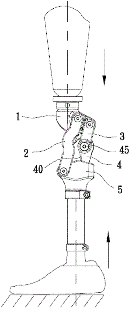
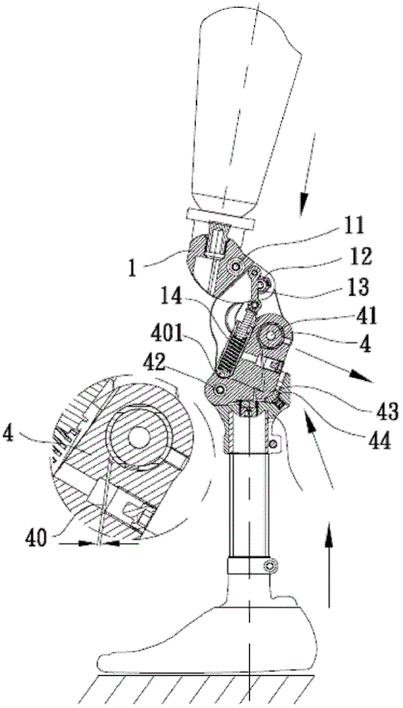
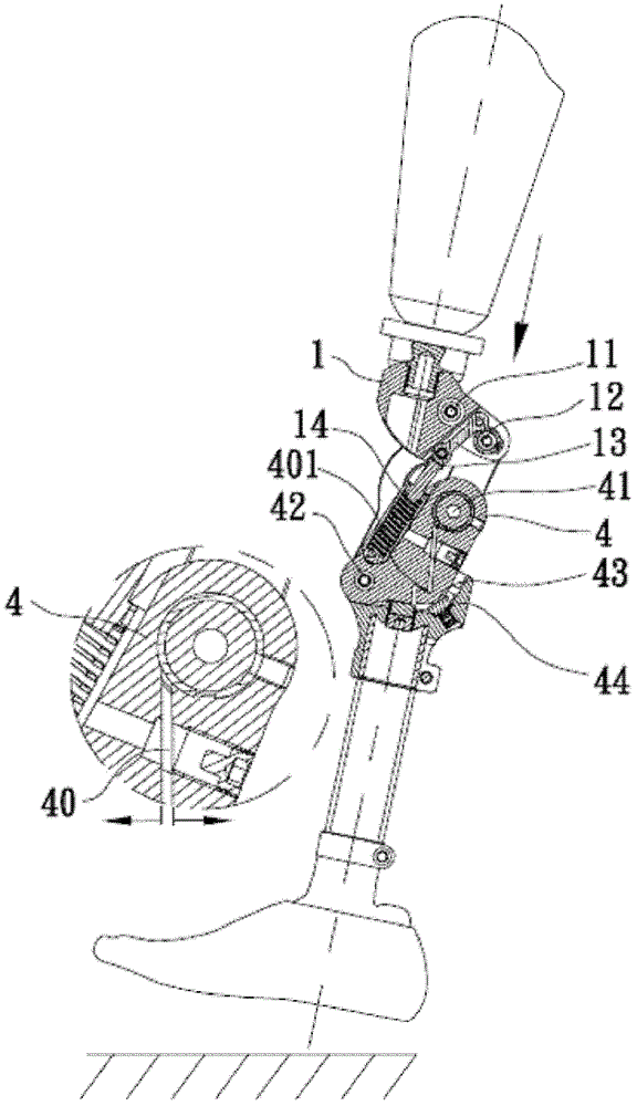
[0022] The structure and function of this creation are described below with a preferred embodiment and detailed description with the drawings to increase the understanding of this creation; this creation is a four-link brake knee joint, please refer to Figure 1 ~ Figure 6 As shown in the middle figure, the main components include the knee seat 1, the first connecting rod 2, the second connecting rod 3, the clamp 4 and the Opel body 5, among them;

[0023] See as Figure 1 ~ Figure 6 As shown, the knee bearing 1 is provided with a front perforation 11 and a rear perforation 12, the upper part can be connected to the prosthetic bearing tube, and the inner connecting rod 13 is provided on the inner side to connect the buffer assembly 14; an Opel body 5 is provided with Opel body perforations in the front, There is a pressure block 44 at the rear, the pressure block 44 can adjust the amount of protrusion; two symmetrical first connecting rods 2, the upper end is connected to the front...


PUM


Abstract

This creation is a four-link brake knee joint. The knee bearing is provided with front and rear perforations, and an inner link is provided on the inside to connect the buffer component; block; two first connecting rods, the upper end of which is connected to the knee bearing and has a hole in front of it, and the lower end of which is connected to the opal body and has a hole; two second connecting rods, whose upper end is connected to the knee bearing and has a hole in the back; a bunch of clamps, which are arranged on the first connecting rod and On the inside of the second connecting rod, the upper end is provided with an upper perforation, and the lower end of the front is provided with a lower perforation. The upper perforation is connected to the lower end of the second link through the axis. The lower perforation corresponds to the Ober body perforation. The rear end of the bundle clamp is in contact with the pressure block; the upper perforation is provided with a gap, the gap is provided with more than one bending section, and extends downward from the upper perforation to the bottom of the bundle clamp, and the gap opening is located between the lower perforation and the rear end of the bundle clamp.

Description

Technical field [0001] This creation is a four-bar brake knee joint. It uses the weight of the body or the reaction force of the heel of the prosthetic limb to contact the ground to reduce the gap set by the clamp to limit the axis rotation, so as to avoid the prosthetic knee joint from bending suddenly during easy standing or walking. Cause danger. Background technique [0002] A good prosthetic knee joint can provide different center of gravity support and corresponding cushioning in different gait cycles or standing states. At the same time, the prosthetic knee joint needs to be equipped with appropriate safety structures during walking or bending of the center of gravity to prevent Suddenly bend and cause danger. [0003] Such as Figure 7 As shown, the prosthetic user is standing without bending the knee joints, and the feet can usually stably support the body weight. As the standing time increases, the knee joints need to be slightly bent or the center of gravity changes to a...

Claims


Application Information

Patent Timeline
Patent Type & Authority Patents(China)
IPC IPC(8): A61F2/64
CPCA61F2/644
Inventor 郑嘉宝吴复国
Owner KEN DALL ENTERPRISE
Learn More