
Method and equipment for obtaining base plates

A technology of substrates and equipment, applied in the field of obtaining substrates, can solve the problems of long movement distance, lower production efficiency, and increase the time loss of obtaining substrates, etc., to achieve the effects of shortening the movement distance, improving production efficiency, and reducing time loss

Inactive Publication Date: 2012-08-22
BOE TECH GRP CO LTD +1
View PDF3 Cites 0 Cited by
  • Summary
  • Abstract
  • Description
  • Claims
  • Application Information

AI Technical Summary

Problems solved by technology

[0005] The present invention provides a method and equipment for obtaining a substrate, which is used to solve the problem of the lengthy movement distance when the downstream equipment obtains the substrate in the prior art, thereby increasing the time for obtaining the substrate Loss, the problem of reducing production efficiency

Method used


Image

  • Method and equipment for obtaining base plates
  • Method and equipment for obtaining base plates
  • Method and equipment for obtaining base plates

Examples


Embodiment 1

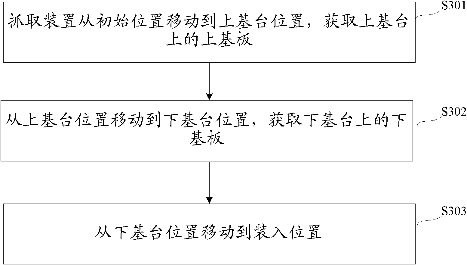
[0054] In this embodiment, the control device controls the specific actions of the grabbing device according to time detection, such as Figure 5 shown, including the following steps:

[0055] S501: The grasping device moves from the initial position to the position of the upper base according to the first control instruction sent by the control device, and acquires the upper substrate on the upper base;

[0056] S502: After the interval between sending the first control instruction reaches the preset first time, the control device sends a second control instruction to the grabbing device, and the grabbing device starts from the base station according to the second control instruction The position is moved to the position of the lower abutment, and the lower substrate on the lower abutment is obtained;

[0057] S503: After the interval between sending the second control instruction reaches the second preset time, the control device sends a third control instruction to the gra...

Embodiment 2

[0060] In this embodiment, the control device controls the specific actions of the grasping device according to the motion detection, such as Figure 6 shown, including the following steps:

[0061] S601: The grabbing device moves from the initial position to the position of the upper base according to the first control instruction sent by the control device, and acquires the upper substrate on the upper base;

[0062] S602: After the control device detects that the grasping device has acquired the upper substrate, it sends a second control instruction to the grasping device, and the grasping device moves from the position of the upper base to the position of the lower base according to the second control command, obtaining the lower substrate on the lower abutment;

[0063] S603: After detecting that the grabbing device has acquired the lower substrate, the control device sends a third control command to the grabbing device, and the grabbing device moves from the position of...


PUM


Abstract

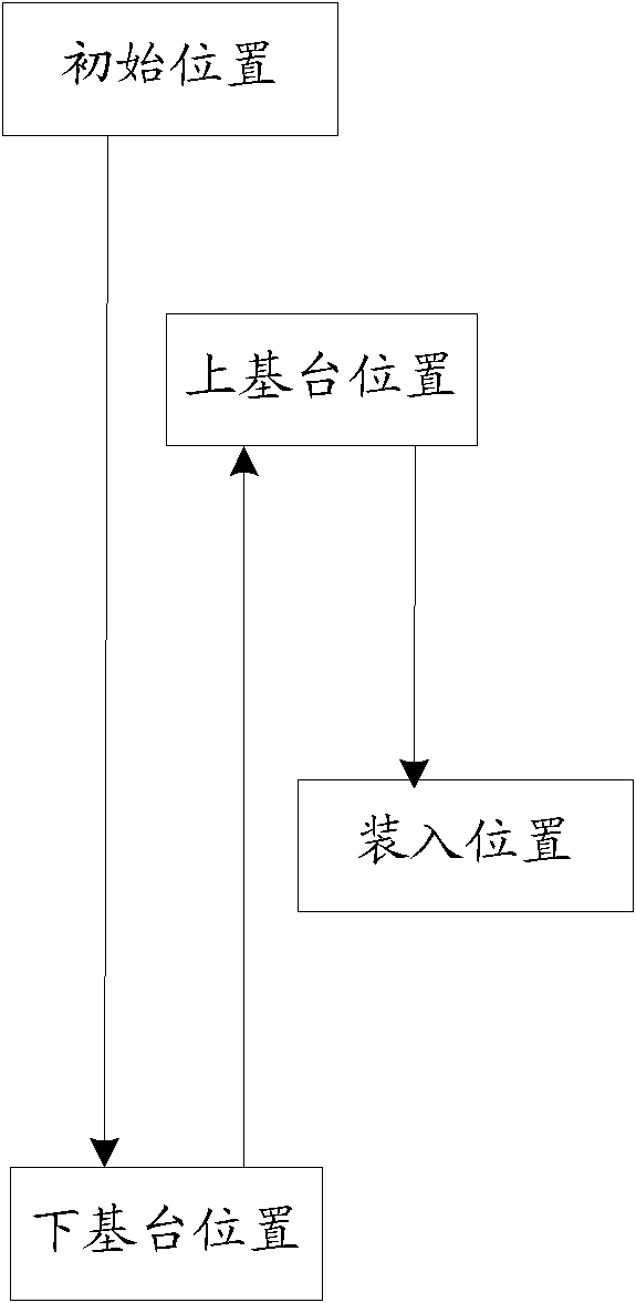
The invention discloses a method and equipment for obtaining base plates. The method comprises the following steps that: a capture device moves to an upper base table position from an initial position to obtain an upper base plate arranged on the upper base table; the capture device moves to a lower base table position from the upper base table position to obtain a lower base plate arranged on a lower base table; and the capture device moves from the lower base table position to a loading position, wherein the upper base table position is higher than the lower base table position, the initial position is higher than the upper base table position, and the loading position is lower than the upper base table position and is higher than the lower base table position. The method and the equipment for obtaining the base plates provided by the embodiment of the invention have the advantages that the base plate arranged on the upper base table is firstly obtained, then, the base plate arranged on the lower base table is obtained, the moving path is shortened through changing the moving track of the capture device, the time loss for obtaining the base plates is reduced, and the production efficiency is improved.

Description

technical field [0001] The invention relates to the technical field of liquid crystal display, in particular to a method and equipment for obtaining a substrate. Background technique [0002] Liquid crystal display, as an important flat panel display method, has developed rapidly in the past ten years. Liquid crystal displays have the advantages of lightness, thinness, and low energy consumption, and are widely used in modern information equipment such as televisions, computers, mobile phones, and digital cameras. [0003] A liquid crystal panel generally consists of an array substrate, a color filter substrate and a liquid crystal layer between the two substrates. In the production process of the liquid crystal panel, firstly, the array substrate and the color filter substrate need to be produced by the upstream equipment through a certain process. The substrate is placed on the upper base of the upstream equipment, and the color filter substrate is placed on the lower ba...

Claims


Application Information

Patent Timeline
IPC IPC(8): G02F1/1333
Inventor 余峰
Owner BOE TECH GRP CO LTD
Learn More