Method for automatically determining scanning area based on positioning image

A technology for scanning areas and locating images, which is applied in the field of medical imaging, can solve problems such as unfavorable and multi-operation time, and achieve the effects of saving time, saving time loss, and submitting inspection efficiency

Inactive Publication Date: 2017-10-20
SHANGHAI UNITED IMAGING HEALTHCARE
View PDF4 Cites 15 Cited by
  • Summary
  • Abstract
  • Description
  • Claims
  • Application Information

AI Technical Summary

Problems solved by technology

Generally speaking, the operator needs to perform multi-step mouse operations (such as clicking, dragging, zooming in, etc.) to accurately locate the starting position and the ending position, which will cause the operator to spend more operating time, which is not conducive to the daily average Hospital with a large outpatient volume

Method used


Image

  • Method for automatically determining scanning area based on positioning image
  • Method for automatically determining scanning area based on positioning image
  • Method for automatically determining scanning area based on positioning image

Examples


Embodiment Construction

[0020] In order to more clearly illustrate the technical solutions of the embodiments of the present application, the following briefly introduces the drawings that need to be used in the description of the embodiments.

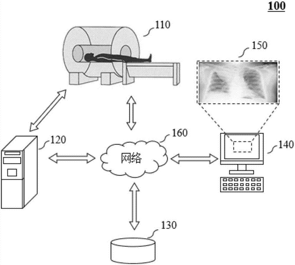
[0021] figure 1 is a CT scanning system 100 according to some embodiments of the present application. Such as figure 1 As shown, the CT scanning system 100 includes a data collection device 110 , a control device 120 , a storage device 130 and an interaction device 140 . The data acquisition device 110 , the control device 120 , the storage device 130 and the interaction device 140 may communicate with each other through the network 160 . In some embodiments, the control device 120 can directly communicate with the data collection device 110 , the storage device 130 and the interaction device 140 without going through the network 160 . In other embodiments, the scanning system may also be a CBCT scanning system, etc., which are not limited in this applicat...


PUM


Abstract

A method for automatically determining a scanning area includes: acquiring a positioning image; identifying at least one characteristic position of the positioning image; and automatically setting a scanning area on the positioning image according to the at least one characteristic position, wherein the scanning area includes an initial position and a termination position, and the automatically setting a scanning area on the positioning image includes automatically setting the initial position and/or the termination position at the at least one characteristic position. The method or system described in the present application can reduce the operator's operation steps to a large extent and can reduce the time loss in clinical scanning.

Description

technical field [0001] The present application relates to the technical field of medical imaging, and more specifically, the present application relates to a method and system for automatically determining a scanning area according to a positioning image. Background technique [0002] At present, in computed tomography (Computed Tomography, CT), before a formal scan diagnosis, a positioning image scan is required, and a scan plan is determined by a doctor or a technician based on the positioning image. Usually, operators such as doctors or technicians need to manually adjust the scanning position according to the positioning image. For example, for a head scan, the operator needs to manually position the start position of the scan plan box (Planbox) to the upper edge of the skull on the operating platform; then manually adjust the end position of the Planbox to cover the entire head area. Generally speaking, the operator needs to perform multi-step mouse operations (such as...

Claims


Application Information

Patent Timeline
Patent Type & Authority Applications(China)
IPC IPC(8): G06K9/20A61B6/03
CPCA61B6/032A61B6/54A61B6/545G06V10/22G06V2201/03
Inventor 蔡鹏飞
Owner SHANGHAI UNITED IMAGING HEALTHCARE
Why Eureka
Try Eureka