Three-dimension flow line placing method with basically uniform intervals

A streamline and three-dimensional technology, applied in the field of scientific computing visualization, can solve problems such as unsatisfactory performance and efficiency of the three-dimensional streamline placement method, large amount of calculation, and complex flow field topology analysis algorithm, etc., to achieve uniform distribution and calculation The effect of small amount and high execution efficiency

Inactive Publication Date: 2012-08-22
BEIJING INSTITUTE OF TECHNOLOGYGY
View PDF2 Cites 12 Cited by
  • Summary
  • Abstract
  • Description
  • Claims
  • Application Information

AI Technical Summary

Problems solved by technology

Flow field topology analysis is not only complex algorithm, but also a lot of calculation
Therefore, the 3D streamline placement method of Ye et al. is less than ideal in terms of performance and efficiency

Method used


Image

  • Three-dimension flow line placing method with basically uniform intervals
  • Three-dimension flow line placing method with basically uniform intervals
  • Three-dimension flow line placing method with basically uniform intervals

Examples


Embodiment Construction

[0033] The preferred embodiments of the present invention will be specifically described below in conjunction with the accompanying drawings.

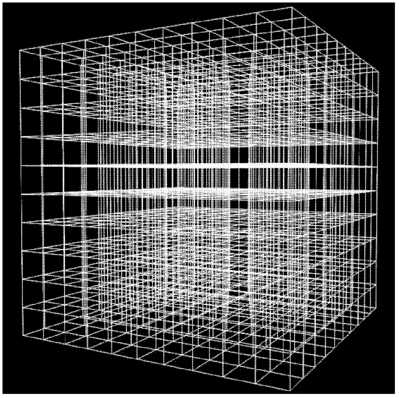
[0034] For the definition in the region D=[x min , x max ]×[y min ,y max ]×[z min ,z max ] in the three-dimensional flow field F: (x, y, z) α (u, v, w), its domain is usually discretized into a rectangular grid unit C i,j,k (i=1, Λ, M, j=1, Λ, N, k=1, Λ, K), at the center of each grid cell (x i,j,k ,y i,j,k ,z i,j,k), there is a vector (u i,j,k , v i,j,k ,w i,j,k ). This discretized three-dimensional flow field is the object to be dealt with in the specific implementation process of the present invention.

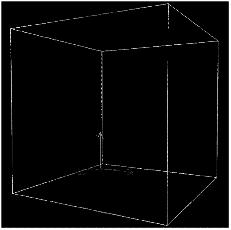
[0035] In order to demonstrate the embodiment of the present invention, a three-dimensional helical flow field is taken as an example. The example flow field is as figure 1 As shown, its definition domain D=[0,10]×[0,10]×[0,10]. figure 1 The three arrows in different colors represent the directions of the XYZ coordina...


PUM


Abstract

The invention relates to a three-dimension flow line placing method with basically uniform intervals and belongs to the technical field of scientific calculation visualization. The method comprises the following steps that: 1, for a given three-dimension flow field, a three-dimension orthogonality control lattice with a definition domain corresponding to the given three-dimension flow field is built; 2, any one six-communication blank region is freely found in the three-dimension orthogonality control lattice, and the found six-communication blank region is set to be R; 3, a flow line seed point is selected in the six-communication blank region R obtained in the step 2; 4, the flow lines passing through the points are calculated and obtained according to the flow line seed points obtained in the step 3; 5, the flow lines obtained in the step 4 are used as new flow lines to be placed into the flow field, and the counting values of the control lattice units related by the flow lines are updated, i.e. 1 is added to the counting values of each control lattice unit related by the flow lines; 6, the step 2, the step 3, the step 4 and the step 5 are repeated until any blank six-communication region does not exist in the three-dimension control lattice; and 7, the flow line placing process is completed, and all flow line placing work is completed.

Description

technical field [0001] The invention relates to a streamline-based flow field visualization method, in particular to a three-dimensional streamline placement method with substantially uniform intervals, and belongs to the technical field of scientific calculation visualization. Background technique [0002] In the field of engineering and scientific research, it is often necessary to visualize the flow field, and convert the invisible flow field simulation data or test data into visible flow field images. Among the existing flow field visualization technologies and methods, streamline is one of the most commonly used methods, because streamline can show the flow field pattern more intuitively. However, flow field visualization based on streamlines faces the problem of how to place streamlines in the flow field. Only by placing an appropriate number of streamlines at appropriate positions in the flow field can a better visualization of the flow field be established. Too few...

Claims


Application Information

Patent Timeline
Patent Type & Authority Applications(China)
IPC IPC(8): G06T17/20
Inventor 张文耀孙波宁建国
Owner BEIJING INSTITUTE OF TECHNOLOGYGY
Why Eureka
Try Eureka