Parallel flow line placing method applicable to two-dimensional flow field

A two-dimensional flow field and streamline technology, applied in the field of scientific computing visualization, can solve problems such as visual confusion, large differences in the interval between streamlines, and no clear method for placing parallel streamlines. The effect of the streamline distribution is basically uniform

Inactive Publication Date: 2013-12-25
BEIJING INSTITUTE OF TECHNOLOGYGY
View PDF1 Cites 0 Cited by
  • Summary
  • Abstract
  • Description
  • Claims
  • Application Information

AI Technical Summary

Problems solved by technology

the result is: figure 2 did not appear figure 1 Pseudo-boundary shown; however figure 2 The streamline spacing varies greatly, some areas have many streamlines clustered together, and some areas do not fill enough streamlines, resulting in visual clutter
This is unacceptable for the streamline placement problem
[0008] Due to the above reasons, there is no clearly proposed and feasible parallel streamline placement method

Method used


Image

  • Parallel flow line placing method applicable to two-dimensional flow field
  • Parallel flow line placing method applicable to two-dimensional flow field
  • Parallel flow line placing method applicable to two-dimensional flow field

Examples


Embodiment Construction

[0049] The preferred embodiments of the present invention will be specifically described below in conjunction with the accompanying drawings.

[0050] For the definition in the region D=[x min , x max ]×[y min ,y max ] in the two-dimensional flow field F: (x, y)a(u, v), its domain is usually discretized into a rectangular grid unit C i,j (i=1, L M, j=1, L, N), at the center of each grid cell (x i,j ,y i,j ), there is a vector (u i,j , v i,j ). This discretized two-dimensional flow field is the object to be dealt with in the specific implementation process of the present invention.

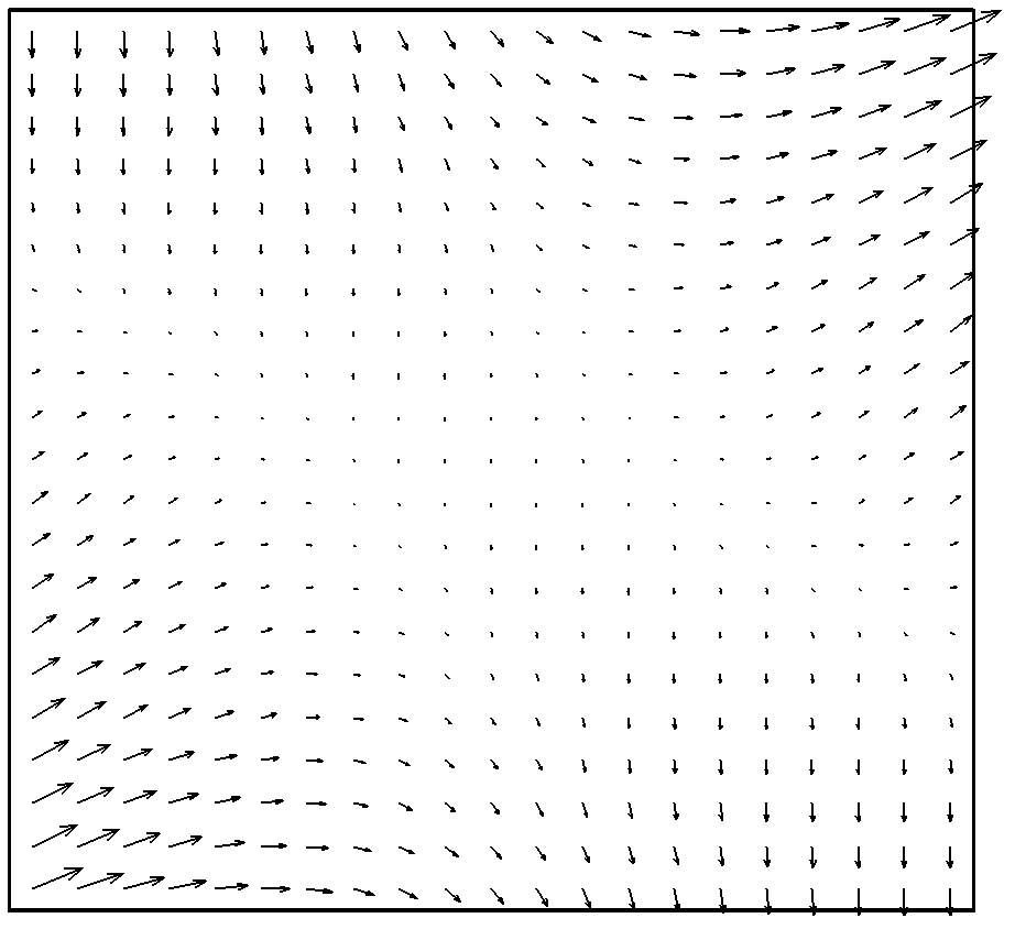
[0051] As an example, image 3 A discretized 2D flow field is shown by vector arrows. The domain of definition of the flow field is: [-2, 2]×[2, 2], and the vector (u, v) at any sampling point (x, y) is defined as:

[0052] u = 1 2 ...


PUM


Abstract

The invention relates to a parallel flow line placing method applicable to a two-dimensional flow field. The parallel flow line placing method comprises the following steps: for a given two-dimensional flow field, defining a closed area which is surrounded by flow lines, critical points with a zero speed or the boundary of the flow field in the flow field as a virtual topological area (VTA) of the flow field, additionally arranging one orthogonal control grid covering the whole flow field, arranging one counter for recording the number of the flow lines for each grid unit, using the defined area of the whole flow field as one initial VTA, selecting one seed point in the VTA, calculating to obtain one flow line, placing the flow line in the VTA, updating the count value of the flow line of the relevant grid unit, segmenting a VTA into one or two new VTAs by the flow line placed in the VTA, and placing the flow line in a parallel way in the new VTA according to a similar processing strategy. By using the parallel flow line placing method, the flow line placing process is effectively accelerated, the problems of a pseudo boundary and visual confusion do not exist, the flow line placing quality is guaranteed, and the parallel flow line placing method is applicable to the visualization of a large-scale flow field.

Description

technical field [0001] The invention relates to a streamline-based parallel visualization method for a flow field, in particular to a parallel streamline placement method suitable for a two-dimensional flow field, and belongs to the technical field of scientific calculation visualization. Background technique [0002] In the fields of fluid mechanics and aerodynamics, in order to analyze the movement of fluid, it is necessary to visualize the flow field, and convert the invisible flow field simulation data or flow field test data into visible flow field images. At present, a variety of technologies and methods have been developed for flow field visualization, such as streamline technology, flow surface technology, geometric icon method, texture synthesis method and so on. [0003] As far as the two-dimensional flow field is concerned, the streamline is one of the commonly used visualization methods, because the streamline can show the flow field pattern more intuitively. To...

Claims


Application Information

Patent Timeline
Patent Type & Authority Patents(China)
IPC IPC(8): G06T11/00
Inventor 张文耀宁建国王义
Owner BEIJING INSTITUTE OF TECHNOLOGYGY
Why Eureka
Try Eureka