
Stroke limit device used for linear actuator and take-up mechanism thereof

A technology of stroke limit and wire take-up mechanism, applied in electromechanical devices, electric components, control of mechanical energy, etc., can solve the problems of difficult outer tube production, increased component material cost, and cumbersome maintenance.

Active Publication Date: 2012-08-22
第一传动科技股ふん有限公司
View PDF5 Cites 3 Cited by
  • Summary
  • Abstract
  • Description
  • Claims
  • Application Information

AI Technical Summary

Problems solved by technology

[0004] However, although the above structure has the purpose of controlling the stroke limit of the electric cylinder, its switch is arranged inside the outer tube. Therefore, the outer tube must be specially formed with a space for the placement of each switch, which not only makes the production of the outer tube difficult but also relatively expensive. In addition, the switches are respectively located at the two ends of the outer tube. In the maintenance process of the damaged components, most of the components of the electric cylinder must be disassembled, which makes the maintenance quite cumbersome and unnecessary. Convenience; in addition, for some electric cylinders with special shapes or specifications, the aforementioned stroke limiting device cannot be installed and set, and needs to be improved and overcome.

Method used


Image

  • Stroke limit device used for linear actuator and take-up mechanism thereof
  • Stroke limit device used for linear actuator and take-up mechanism thereof
  • Stroke limit device used for linear actuator and take-up mechanism thereof

Examples


Embodiment Construction

[0050] The detailed description and technical content of the present invention are described below with accompanying drawings. However, the attached drawings are provided for reference and illustration only, and are not intended to limit the present invention.

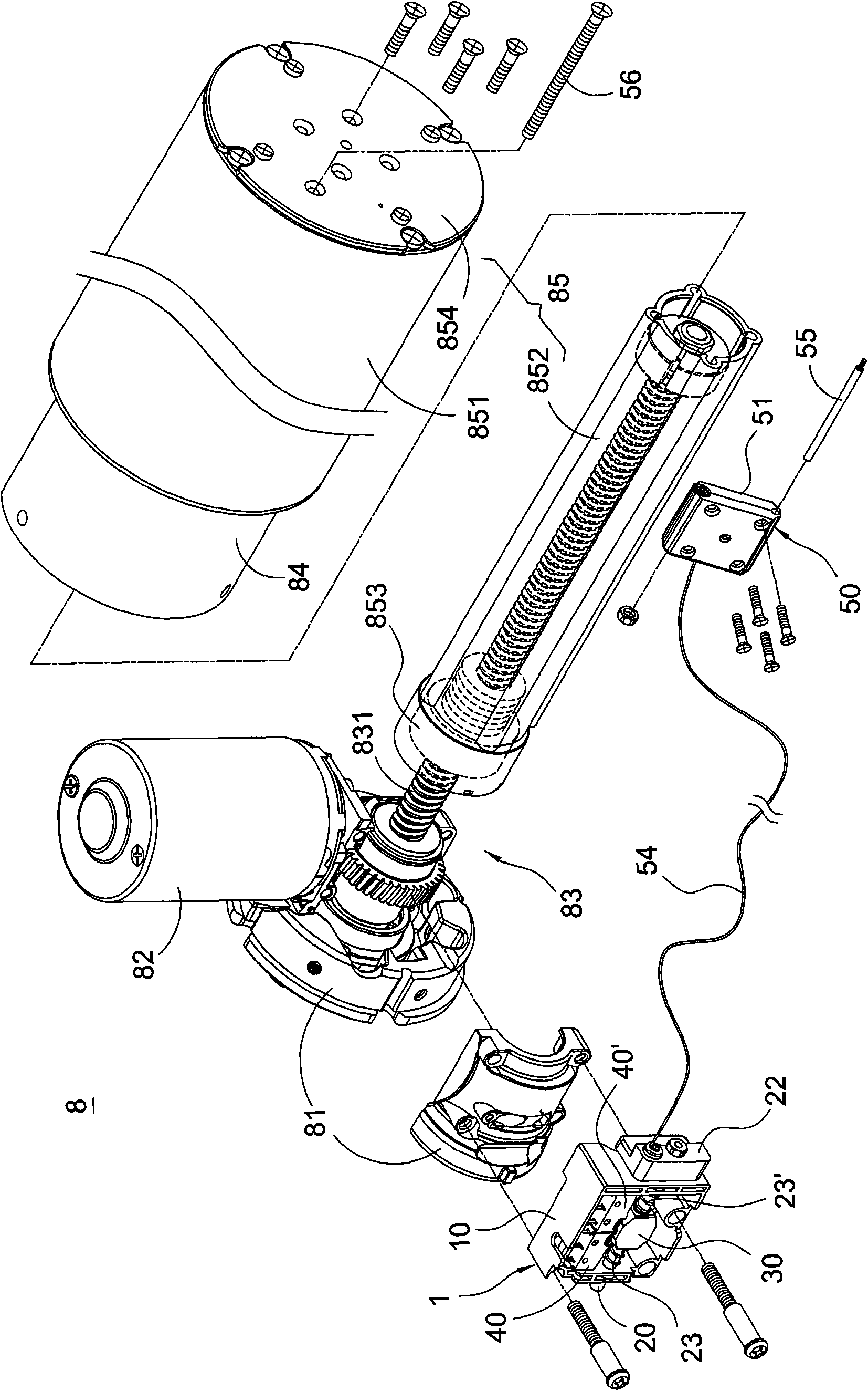
[0051] see figure 1 As shown, the present invention provides a stroke limiting device for an electric cylinder and its take-up mechanism. The stroke limiting device 1 mainly includes a box body 10, a movable member 20, a body 30, a pair of switches 40, 40' and A take-up mechanism 50.

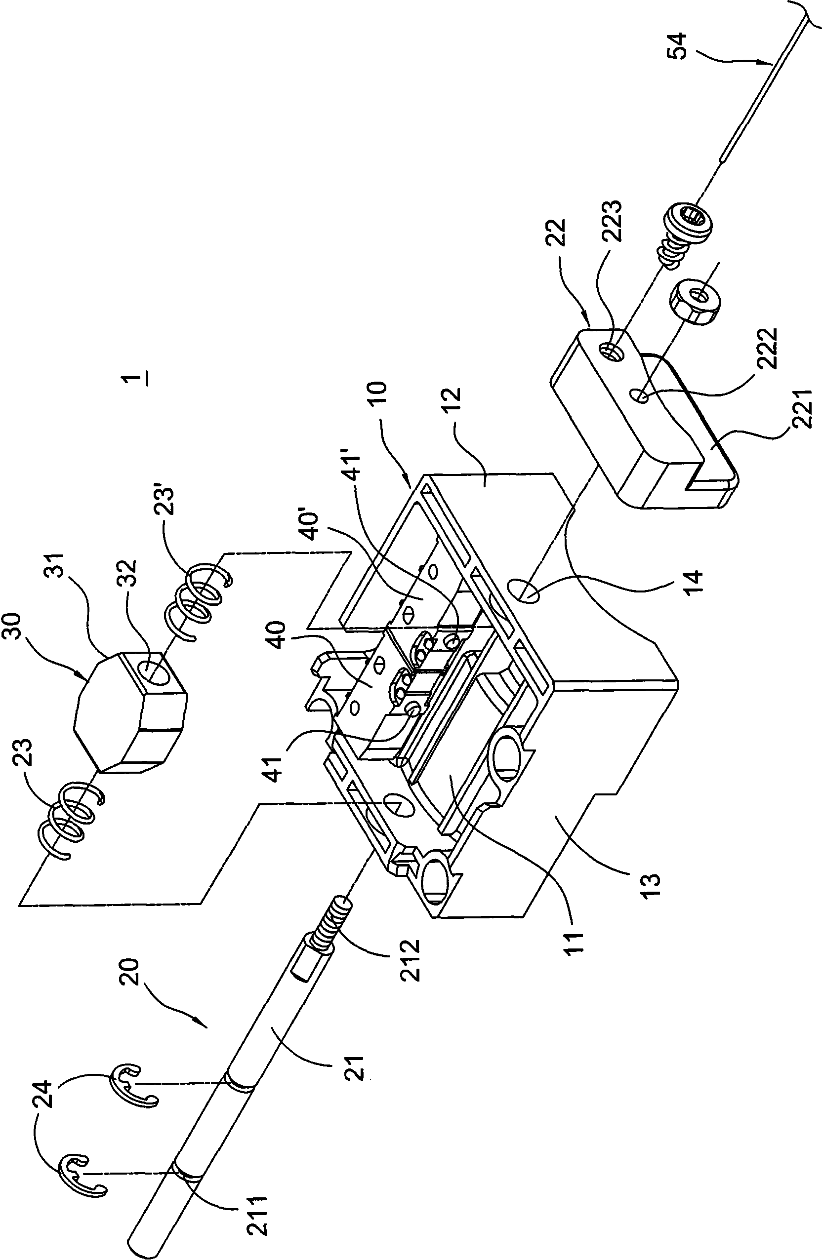
[0052] see figure 2 As shown, the box body 10 can be made of materials such as plastics, and it is mainly composed of a bottom plate 11, a pair of wall plates 12 and a pair of side plates 13 extending upward from the edge of the bottom plate 11, and each wall plate 12 and each The side panels 13 are connected to each other, and each wall panel 12 is provided with a corresponding through hole 14 .

[0053]The movable member 20 include...


PUM


Abstract

The invention discloses a stroke limit device used for a linear actuator and a take-up mechanism thereof. The linear actuator comprises an engine base and an extension tube, and the stroke limit device comprises a box body, a movable component, a block body, a pair of switches and a take-up mechanism. The box body is fixed at the engine base and is provided with a wallboard, and a through hole is arranged at the wallboard. The movable component comprises a rod body which penetrates through the through hole and can move relatively to the box body, and the block body is fixedly connected onto the rod body. The positions of the pair of switches corresponding to the block body are fixedly arranged at the box body, each switch is provided with a triggering part on which the block body touches to generate an electric signal, and the triggering parts are respectively positioned at two phases of different ends of a move path of the block body. The take-up mechanism comprises a line body which is placed in the extension tube and moves along with the extension tube, and one end of the line body is connected with the movable component. Thus, the stroke limit device can utilize the actuating range of small space to control the extreme position of a long distance.

Description

technical field [0001] The invention relates to an electric cylinder, in particular to a stroke limiting device for the electric cylinder and a wire take-up mechanism thereof. Background technique [0002] There are many types of electric cylinders (Linear Actuator) currently on the market, one of which is to assemble an electric motor and an outer tube on a machine base, place a lead screw on the machine base and use the electric motor to drive the lead screw to rotate. A telescopic tube is screwed on the outside of the lead screw, and an outer tube is sleeved on the outside of the telescopic tube, and one end of the outer tube is fixed on the machine base; in this way, the telescopic tube can be driven by the motor, and relative to the outer tube along the axial direction of the lead screw. Although the linear reciprocating displacement is performed, this type of electric cylinder cannot know whether the telescopic tube has moved to the end of the stroke when it is actuate...

Claims


Application Information

Patent Timeline
IPC IPC(8): H02K7/06B65H75/48
Inventor 吴周欣
Owner 第一传动科技股ふん有限公司
Learn More