Head gripper linking mechanism of plug-in machine

A technology of linkage mechanism and plug-in machine, which is applied in the directions of manipulators, manufacturing tools, etc., to achieve the effect of reducing equipment damage

Inactive Publication Date: 2012-09-05
DONGGUAN SCIENCGO MACHINERY MFG
View PDF4 Cites 9 Cited by
  • Summary
  • Abstract
  • Description
  • Claims
  • Application Information

AI Technical Summary

Problems solved by technology

[0004] In addition, if the movement of the worktable of the plug-in machine in the horizontal direction and the movement of the manipulator in the vertical direction are controlled by different drive circuits, when the drive circuit that controls the movement of the manipulator in the vertical direction is partially powered off , there will also be potential safety hazards of the above faults

Method used


Image

  • Head gripper linking mechanism of plug-in machine
  • Head gripper linking mechanism of plug-in machine
  • Head gripper linking mechanism of plug-in machine

Examples


Embodiment Construction

[0021] In order to facilitate the understanding of those skilled in the art, the present invention will be further described below in conjunction with the embodiments and accompanying drawings, and the contents mentioned in the embodiments are not intended to limit the present invention.

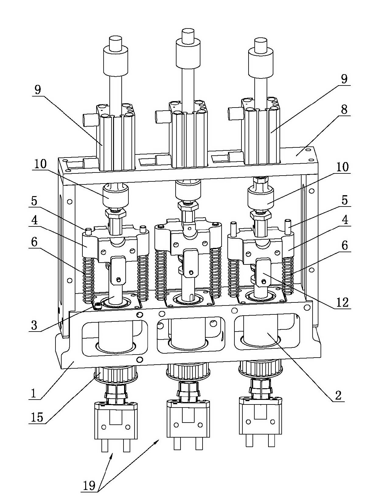
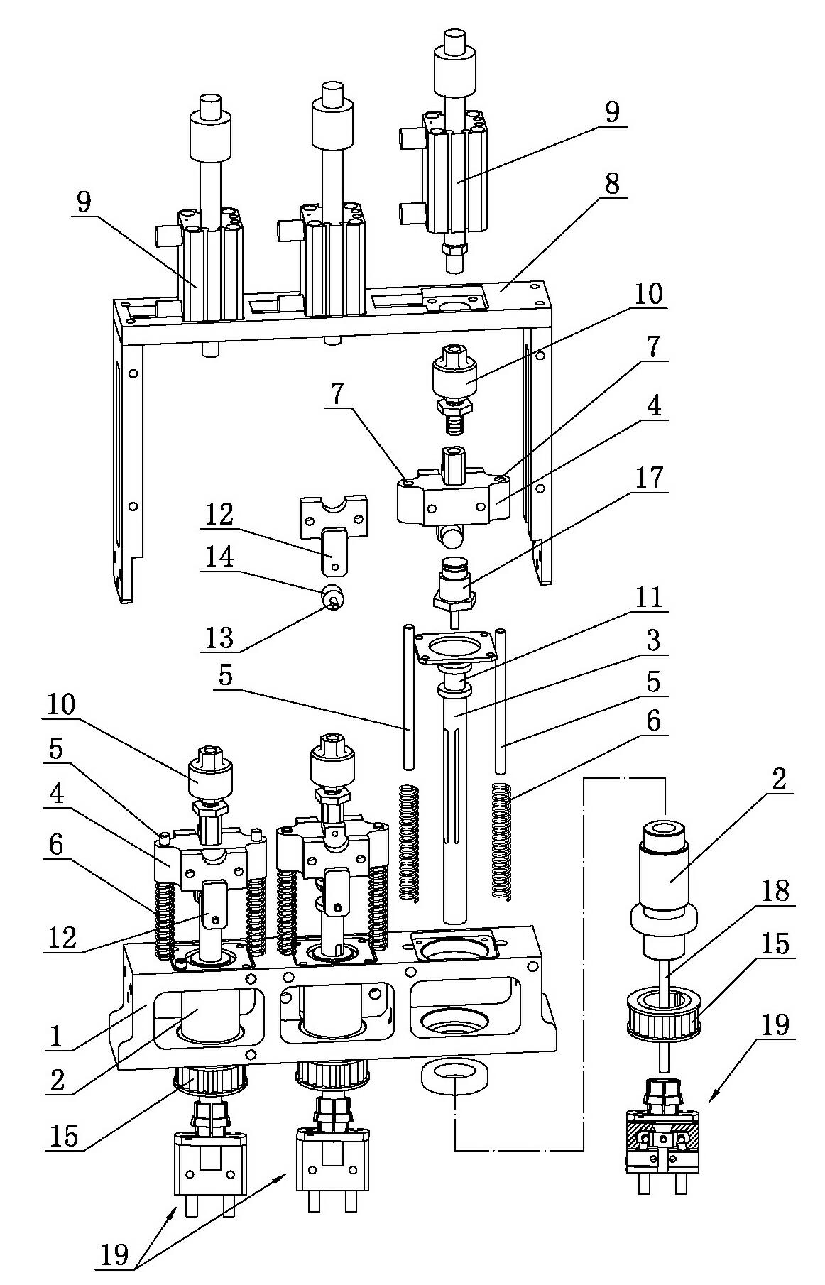
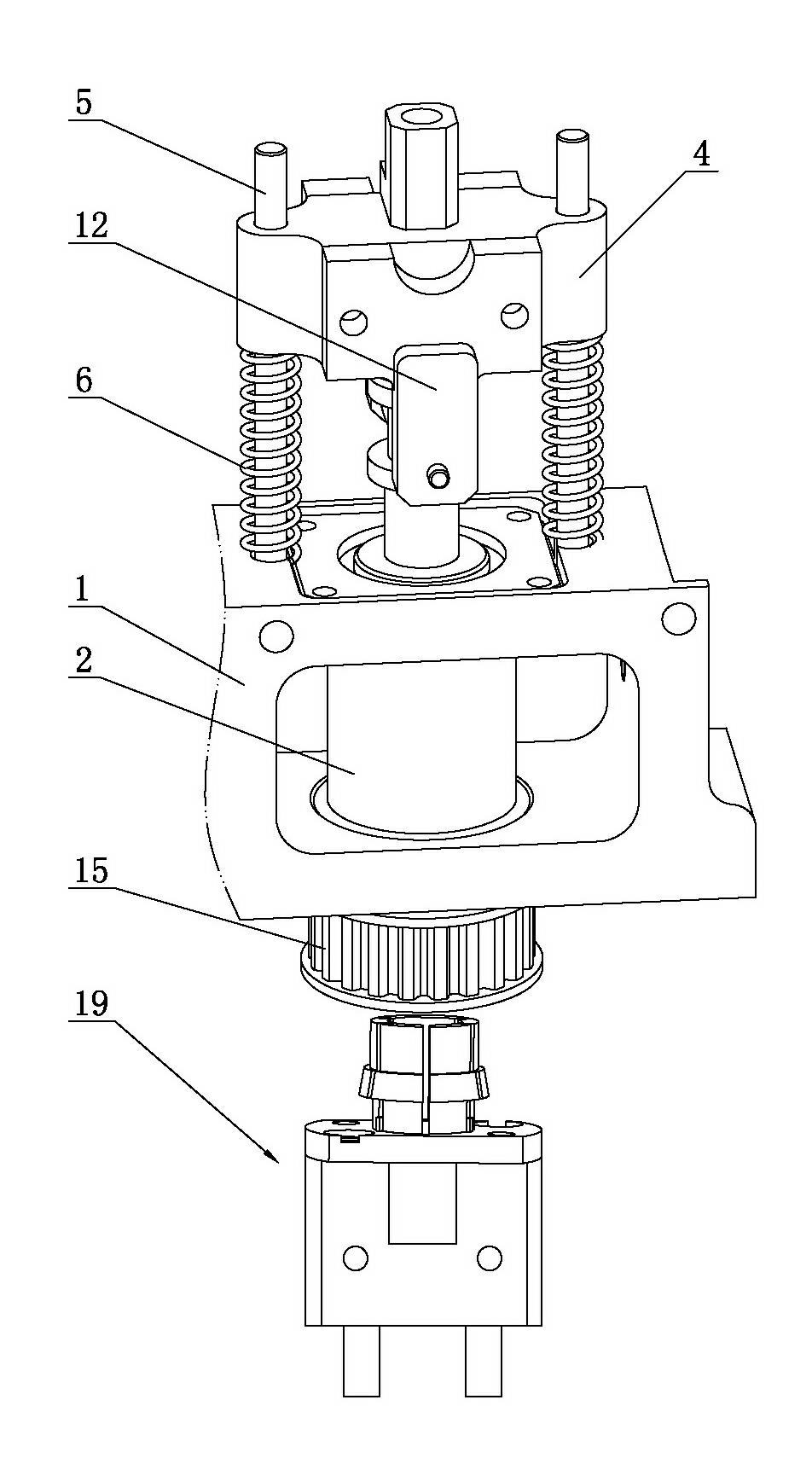
[0022] Such as Figure 1 to Figure 4 As shown, a plug-in machine head claw linkage mechanism includes a mounting body 1 and a spline sleeve 2 rotatably mounted on the mounting body 1. The spline sleeve 2 is fitted with a hollow spline shaft 3, and the hollow spline The upper end of the shaft 3 is equipped with a linkage 4, the installation body 1 is equipped with a driving device for driving the linkage 4 to move up and down, the installation body 1 is equipped with a guide rod 5, and the guide rod 5 is sleeved with a spring 6. The linkage 4 is provided with a through hole 7 through which the guide rod 5 passes, and the two ends of the spring 6 abut against the installation body 1 and the li...


PUM


Abstract

The invention relates to the technical field of plug-in equipment of an electronic element and particularly relates to a head gripper linking mechanism of a plug-in machine. The head gripper linking mechanism of the plug-in machine comprises a mounting body and a spline housing which is rotatably arranged on the mounting body, wherein the spline housing is sleeved with a hollow spline shaft; the upper end of the hollow spline shaft is provided with a linking piece; the mounting body is provided with a driving device for driving the linking piece to move up and down; the mounting body is provided with a guide rod; the guide rod is sleeved with a spring; the linking piece is provided with a through hole and the guide rod penetrates through the through hole; and two ends of the spring are respectively abutted against the mounting body and the linking piece. The head gripper linking mechanism of the plug-in machine disclosed by the invention greatly reduces damages of the plug-in equipment caused by the factor that an air pressure of an air pressure source is insufficient, air is suddenly cut off or power is partially cut off, so that a safety protection function of the head gripper linking mechanism of the plug-in machine is further realized.

Description

technical field [0001] The invention relates to the technical field of electronic component plug-in equipment, in particular to a gripper linkage mechanism at the head of a plug-in machine. Background technique [0002] With the rapid development of the electronics industry, the application of electronic processing equipment is becoming more and more extensive, and the mechanical gripper is a very commonly used device in electronic processing equipment. Electronic processing equipment is mainly used to pick up electronic components, and transport and install them on the PCB. Circuit boards, but the existing electronic processing equipment has a relatively high cost of processing equipment due to its complex structure and high difficulty in control. [0003] In order to reduce the production and processing costs of the equipment, the mechanical claws of the existing electronic component insertion machines are generally driven by air pressure, and the up and down movements of ...

Claims


Application Information

Patent Timeline
Patent Type & Authority Applications(China)
IPC IPC(8): B25J13/00B25J19/00
Inventor 梁发新高喜宏任明哲曾翔清陈卓标
Owner DONGGUAN SCIENCGO MACHINERY MFG
Why Eureka
Try Eureka