Gas flow control device

A technology of air flow control device and control cavity, applied in the direction of control valve, valve device, functional valve type, etc.

Active Publication Date: 2012-09-12
JIANGSU HAINA AIR CONDITIONER PURIFICATION EQUIP
View PDF4 Cites 3 Cited by
  • Summary
  • Abstract
  • Description
  • Claims
  • Application Information

AI Technical Summary

Problems solved by technology

[0003]Existing airflow control devices, especially piston-type airflow control devices, generate negative pressure in the piston cavity to attract the piston when returning air, which is not easy to open and control smoothly The return air path of the device
If one side of the piston chamber is communicated with the atmosphere, although the above-mentioned technical problems can be solved, the place of use will be limited because of the air leakage of the control device.

Method used


Image

  • Gas flow control device
  • Gas flow control device
  • Gas flow control device

Examples


Embodiment 1

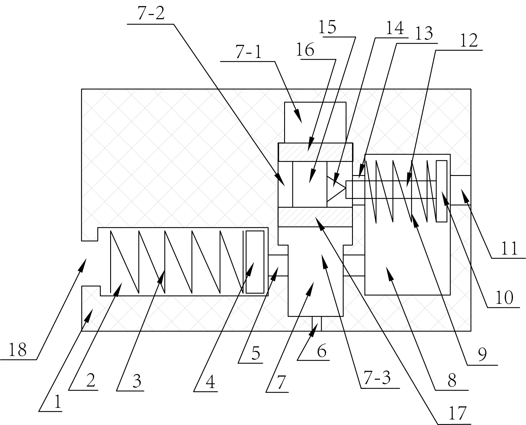
[0022] Such as figure 1 , this embodiment includes a main body 1, in which an inflation and exhaust chamber 7 with an inflation and exhaust port 6, an inflation control chamber 2 with an inflation hole 18 and a deflation control chamber with an exhaust hole 11 are arranged. Cavity 8; an air channel 5 is provided between the inflation and exhaust cavity body 7 and the inflation control cavity 2. An air passage is also provided between the inflation and exhaust cavity body 7 and the deflation control cavity 8 .

[0023] The inflatable control chamber 2 is installed with an inflatable end cap 4 for blocking the air passage 5 between the inflatable and exhaust chamber 7 and the inflatable control chamber 2, and the inflatable end cap 4 is connected to a Inner inflatable end elastomer 3. The deflation control cavity 8 is equipped with a deflation end cap 10 for blocking the vent hole 11, and the deflation end cap 10 is connected with a deflation end elastic body 9 located in the...

Embodiment 2

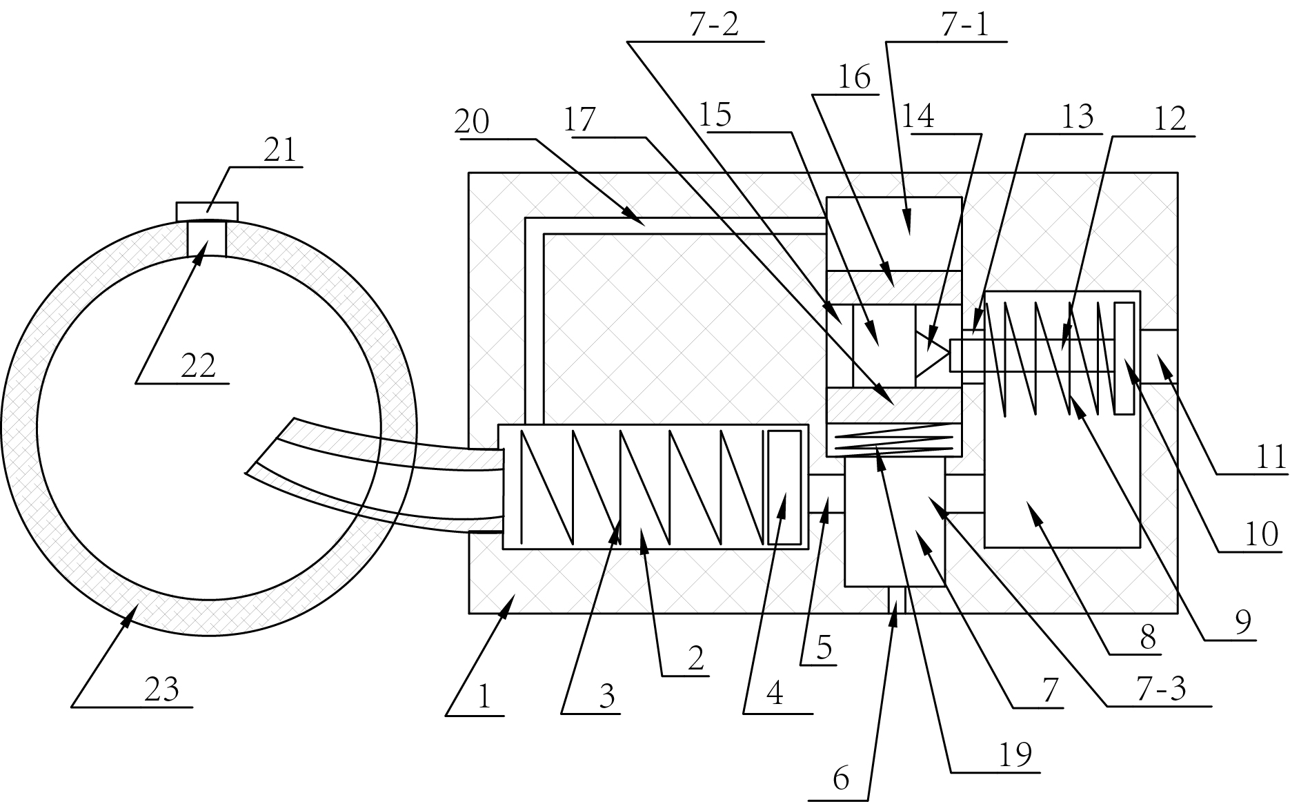
[0026] Such as figure 2 , on the basis of Embodiment 1, this embodiment also includes an auxiliary air bag 23 with an air filling hole 22, and an inflation check valve 21 is installed in the air filling hole 22, and the auxiliary air bag 23 is connected to the air filling hole. 18 in communication; it also includes a control air passage 20 opened in the body 1, one end of the control air passage 20 communicates with the first cavity 7-1, and the other end communicates with the inflation control chamber 2; it also includes a control air passage installed in the second The return elastic body 19 between the sealing head 17 and the cavity wall of the third cavity 7-3. The auxiliary air bag 23 is placed in the air container. The auxiliary airbag 22 is used to inflate an air container (such as an airbag, balloon, pipeline, etc.).

[0027] When inflating the gas container, the gas in the third cavity 7-3 presses against the second head 17, so that the connecting rod 15 moves axia...

Embodiment 3

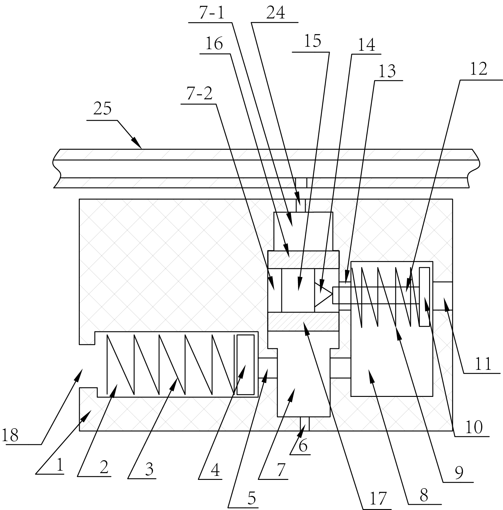
[0029] Such as image 3 , on the basis of Embodiment 1, it also includes a control air pipe 25; and a control air hole 24 communicated with the first cavity 7-1 is opened on the body 1; the control air pipe 25 communicates with the first cavity through the control air hole 24 Body 7-1 is connected.

[0030] When the gas container is deflated, first press the first head 16 by controlling the air pipe 25, so that the outer end of the lock block 14 and the end head rod 12 of the deflation end are separated from extrusion, so as to open the vent hole 11 more smoothly. Then the gas container is deflated by the inflation and deflation control device 3 . During use, control air pipe 25 as normal pressure or high pressure gas as required.


PUM


Abstract

The invention discloses a gas flow control device. A control gas passage is arranged in a body of the gas flow control device, one end of the control gas passage is connected with a cavity in the body, the other end of the control gas passage is connected with a cavity at a gland end of a connecting rod, and the gas flow control device is additionally provided with an auxiliary gas sac. When the gas flow control device is used for inflating, gas flow blocks a gas return passage, an inflating gas passage is opened, and one-way inflation is realized; when gas returns, the gas flow blocks the inflating gas passage, and the gas return passage is smoothly opened under the effect of the auxiliary gas sac; and when either inflation or gas return is not required, the gas flow control device can realize a pressure maintaining function.

Description

[0001] technical field [0002] The invention relates to an airflow control device used as a filling and deflation valve assembly. Background technique [0003] Existing airflow control devices, especially piston-type airflow control devices, generate negative pressure on one side of the piston cavity to attract the piston when returning air, which is not convenient for smoothly opening the return air path of the control device. If one side of the piston chamber is communicated with the atmosphere, although the above-mentioned technical problems can be solved, the place of use will be limited because of the air leakage of the control device. Contents of the invention [0004] The technical problem to be solved by the present invention is to provide an air flow control device that realizes one-way inflation and one-way return air, and can open the return air path of the control device more smoothly when returning air, so as to overcome the disadvantages of existing air v...

Claims


Application Information

Patent Timeline
Patent Type & Authority Applications(China)
IPC IPC(8): F16K15/20
Inventor 吉昌辉
Owner JIANGSU HAINA AIR CONDITIONER PURIFICATION EQUIP
Why Eureka
Try Eureka