
Intelligent camera tracking car model for racing tracks

An intelligent tracking and camera technology, applied in road network navigators, two-dimensional position/channel control and other directions, can solve the problems of affecting the extraction of track information, control redundancy, and not giving full play to the amount of information collected by cameras.

Inactive Publication Date: 2014-04-09
BEIJING INSTITUTE OF TECHNOLOGYGY
View PDF4 Cites 0 Cited by
  • Summary
  • Abstract
  • Description
  • Claims
  • Application Information

AI Technical Summary

Problems solved by technology

[0005] 1. Use fixed look-ahead, that is, take the same line of data for each image to calculate the offset, control the motor and steering gear, do not give full play to the advantages of the large amount of information collected by the camera, and have poor adaptability to curves with different curvatures
[0006] 2. The entire image is binarized with a fixed threshold, which is prone to boundary blurring in the distance and affects the extraction of track information
[0007] 3. The reliability of clear image processing is relatively high, but once the edge of the image is blurred, it is easy to misjudge the situation of missing lines, resulting in the situation where the car runs out of the line, and it cannot be handled well for places with severe distortion in the distance.
[0008] 4. Using traditional PID control, the control of steering gear and motor is realized by debugging a set of PID parameters for a device. This method is too general, and it is very difficult to select and adjust parameters. The formula is applied without careful analysis of the model , control redundancy

Method used


Image

  • Intelligent camera tracking car model for racing tracks
  • Intelligent camera tracking car model for racing tracks
  • Intelligent camera tracking car model for racing tracks

Examples


Embodiment Construction

[0024] The preferred embodiments of the present invention will be specifically described below in conjunction with the accompanying drawings.

[0025] The car model of this embodiment can be divided into an energy supply system, a signal acquisition system, a central processing system, and an execution system.

[0026] (1) Energy supply system

[0027] This car uses a 7.2V / 2000mAh rechargeable Ni-Cd battery as the power supply, and supplies power to the single-chip microcomputer, steering gear, camera, etc. through a booster voltage regulator circuit. The camera is 12V, the single-chip microcomputer is 5V, and the steering gear is -0.7V.

[0028] (2) Signal acquisition and processing system

[0029] This car adopts an automatic dimming Sony CCD camera to collect image information, and takes an image array with 46 rows and 134 columns. In addition, this car model also installed an encoder on the rear axle to collect speed.

[0030] (3) Central processing system

[0031] The...


PUM


Abstract

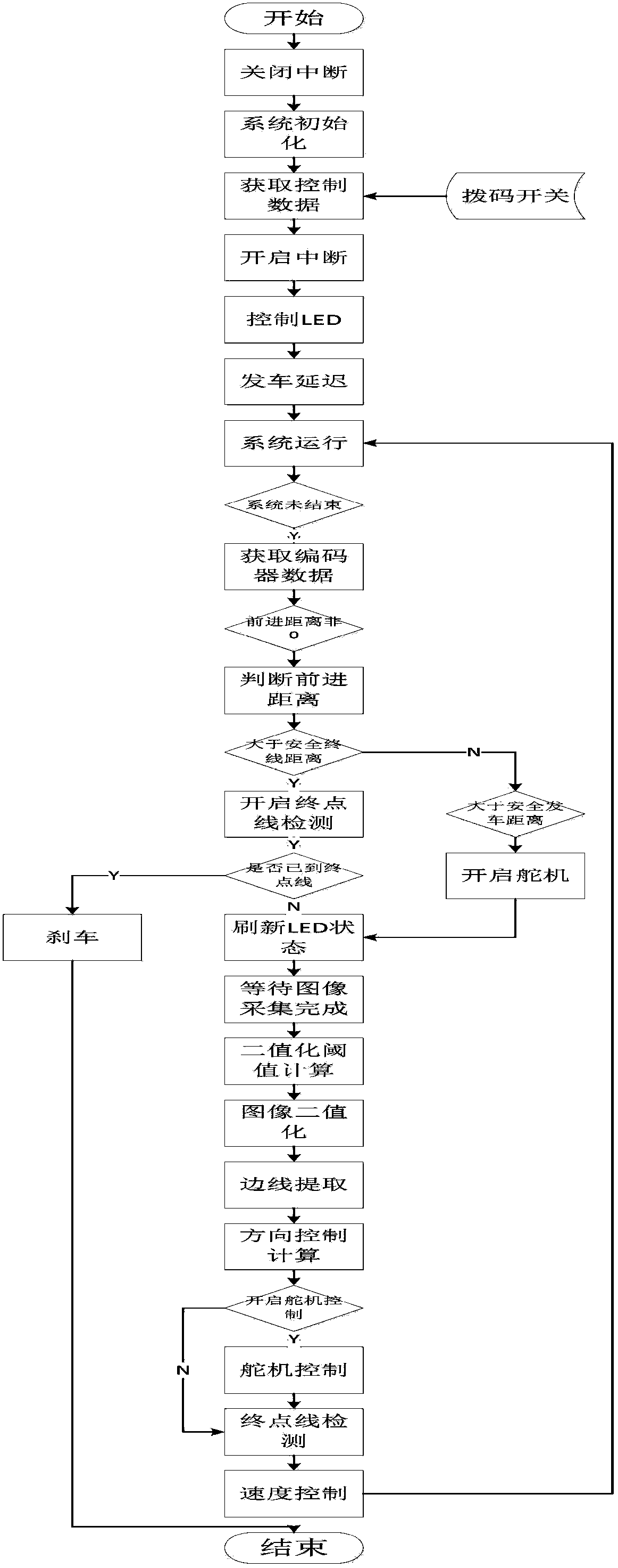
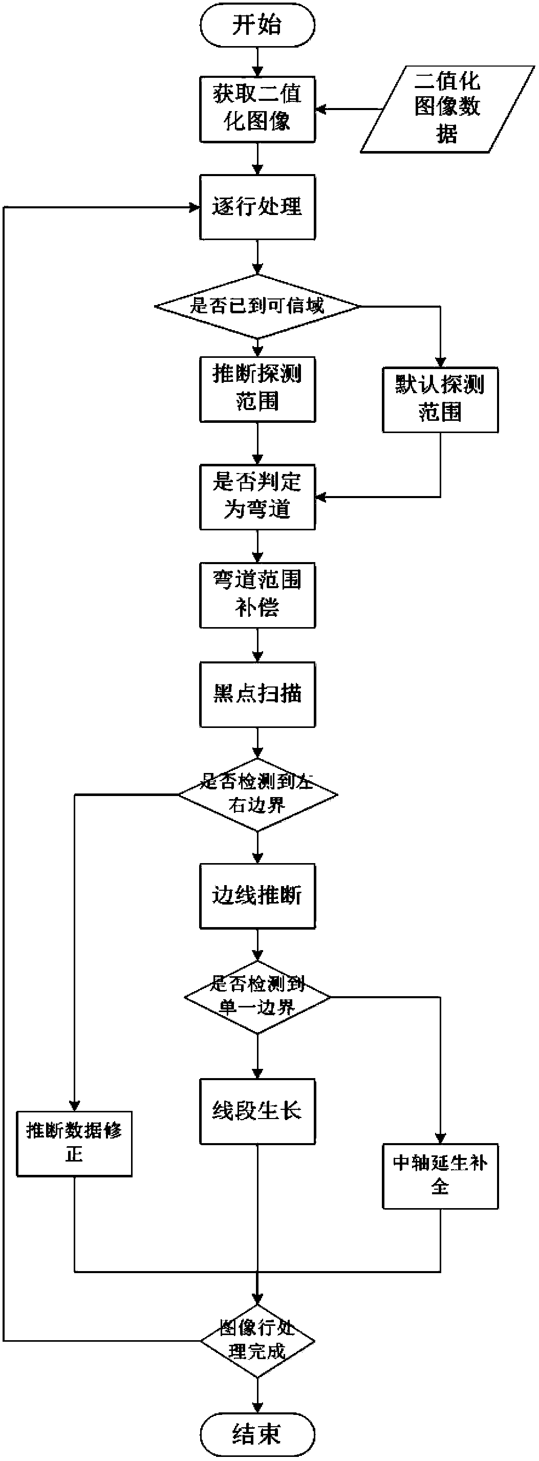
The invention relates to an intelligent camera tracking car model for racing tracks. The intelligent camera tracking car model comprises an energy supply system, a signal collecting system, a central processing system and an executing system; and the central processing system comprises the following processing steps: 1. performing binaryzation on a gray level image collected from the signal collecting system; 2. performing side boundary extraction on the binaryzed image; 3. identifying the racing track according to the extracted side boundary and determining the advancing direction of the car model; 4. calculating the included angle between the optimal advancing direction of the car model and the actual advancing direction of the car model to control a steering engine so as to control the direction; and 5. obtaining the expected speed of the car model through offset, namely, the distance between the axial wire of the car and the axial wire of the racing track, and controlling a drive motor to control the speed. The intelligent camera tracking car model disclosed by the invention fully utilizes the information of a whole frame of image to extract the racing track, thereby overcoming the image fuzzy distortion problem and determining the optimal advancing direction of the car model in real time to realize intelligent tracking of the car model.

Description

technical field [0001] The invention relates to a car model, in particular to a camera intelligent tracking car model for a track. Background technique [0002] Smart tracking car models can be divided into photoelectric, camera and electromagnetic (requiring special wiring) tracking car models according to sensors. The car model detects the path by sensing the alternating magnetic field generated by the wire in the center of the track, which belongs to the electromagnetic sensor method; the car model detects the path by collecting the track image (one-dimensional, two-dimensional) or continuously scanning the reflection points of the track. The camera method; the car model detects the path by collecting the reflection brightness of a few isolated points on the track, which belongs to the photoelectric sensor method. [0003] For the camera tracking car model, it can be divided into energy supply system, signal acquisition system, central processing system, and execution sy...

Claims


Application Information

Patent Timeline
Patent Type & Authority Patents(China)
IPC IPC(8): G05D1/02G01C21/34
Inventor 陈杰浩叶刚钟鸣杨龙王守宽关正马辰井泓杨萍
Owner BEIJING INSTITUTE OF TECHNOLOGYGY
Learn More