Gear pump and mobile unit for adjusting conveying capacity
A mobile unit, gear pump technology, applied in the direction of pump, pump control, machine/engine, etc., can solve the problems affecting the adjustment characteristics, etc., and achieve the effect of simple function and simple switching position
- Summary
- Abstract
- Description
- Claims
- Application Information
AI Technical Summary
Problems solved by technology
Method used
Image

Examples
Embodiment Construction
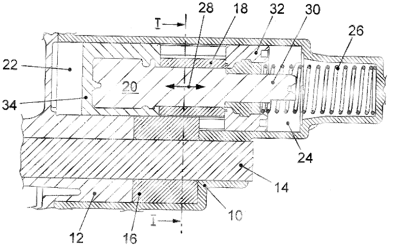
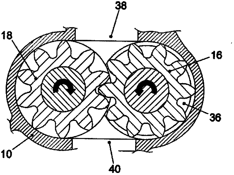
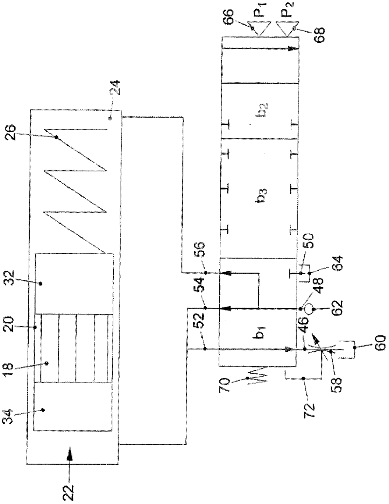
[0021] exist figure 1 and 2 The gear pump according to the invention shown in is designed as an external gear pump as an exemplary embodiment. The gear pump has a pump casing 10 to which a cover 12 is attached. A drive shaft 14 is rotatably mounted in the cover 12 . The drive shaft 14 is connected in a rotationally fixed manner to a drive gear or drive conveyor wheel 16 , which is connected in a toothed manner to a driven gear or conveyor wheel 18 . The gear pump is provided with a displacement unit 20 for changing the delivery volume, which is movably mounted between a first pressure chamber or control chamber 22 and a second pressure chamber or control chamber 24 . A compression spring 26 acting on the displacement unit 20 is accommodated in the second control chamber 24 . It exerts a restoring force on the displacement unit 20 in the direction of the first control chamber 22 .
[0022] The mobile unit 20 is axially displaceable according to the double-headed arrow 28 a...
PUM
 Abstract
Description
Claims
Application Information
 - R&D
- Intellectual Property
- Life Sciences
- Materials
- Tech Scout
- Unparalleled Data Quality
- Higher Quality Content
- 60% Fewer Hallucinations
Browse by: Latest US Patents, China's latest patents, Technical Efficacy Thesaurus, Application Domain, Technology Topic, Popular Technical Reports.
© 2025 PatSnap. All rights reserved.Legal|Privacy policy|Modern Slavery Act Transparency Statement|Sitemap|About US| Contact US: help@patsnap.com