A mid-suction gasification furnace

A gasification furnace and furnace body technology, applied in the direction of incinerators, combustion types, combustion methods, etc., can solve the problems of inconvenient disassembly and transportation, inconvenient operation, inconvenient cleaning of ashes, etc., to achieve convenient handling and transportation, convenient cleaning and disassembly, and convenient stored effect

Active Publication Date: 2022-06-28
北京鼎胜投资管理有限公司
View PDF6 Cites 0 Cited by
  • Summary
  • Abstract
  • Description
  • Claims
  • Application Information

AI Technical Summary

Problems solved by technology

The gasification furnace is a kind of burning appliance with environmental protection, energy saving and cleanness, which is suitable for the use of farmers in rural areas and towns. It plays an important role in garbage cleaning. Due to its structural problems, the existing garbage disposal equipment cannot After dust removal and flue gas filtration, it is difficult to avoid secondary air pollution
[0003] In the process of realizing the present invention, the inventors found that at least the following problems in the prior art have not been resolved: 1. After the existing gasification furnace has undergone incineration, the accumulated ashes are inconvenient to clean up, thereby affecting the normal operation of the machine; 2. The structure of the existing gasification furnace is fixed, and most of them are integrated welding, which is inconvenient to disassemble and transport; 3. During the operation of the furnace body, it is necessary to supply water to the furnace from time to time. The existing water supply tank mechanism is fixed and relatively heavy. It is inconvenient to disassemble; 4. During the operation of the furnace body, it is necessary to use the wind force of the induced draft fan to draw the airflow to generate negative pressure in the furnace. The induced draft fan mechanism is fixed, and the height of each layer of the furnace body is different, which makes the operation inconvenient and time-consuming

Method used


Image

  • A mid-suction gasification furnace
  • A mid-suction gasification furnace
  • A mid-suction gasification furnace

Examples


Embodiment Construction

[0037] The technical solutions in the embodiments of the present invention will be clearly and completely described below with reference to the accompanying drawings in the embodiments of the present invention. Obviously, the described embodiments are only a part of the embodiments of the present invention, but not all of the embodiments. Based on the embodiments of the present invention, all other embodiments obtained by those of ordinary skill in the art without creative efforts shall fall within the protection scope of the present invention.

[0038] see Figure 1 to Figure 9 , the present invention provides a kind of technical scheme:

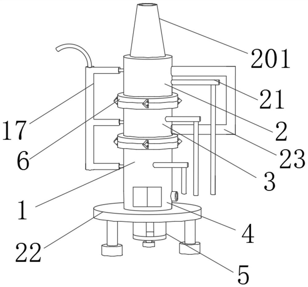
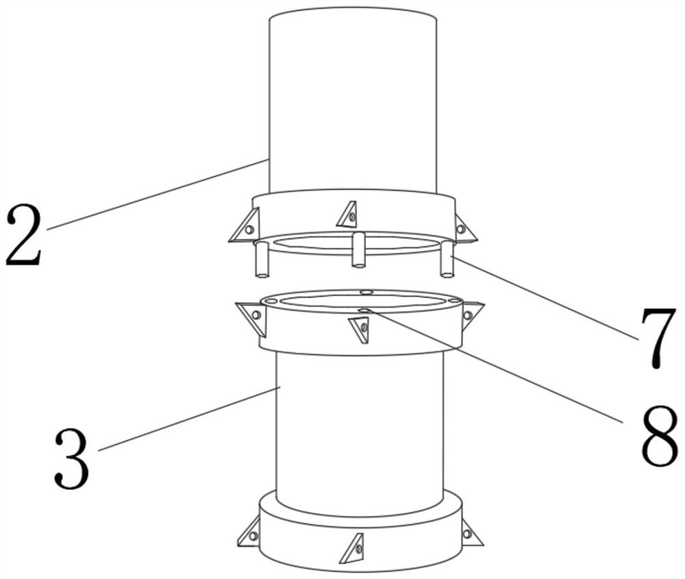
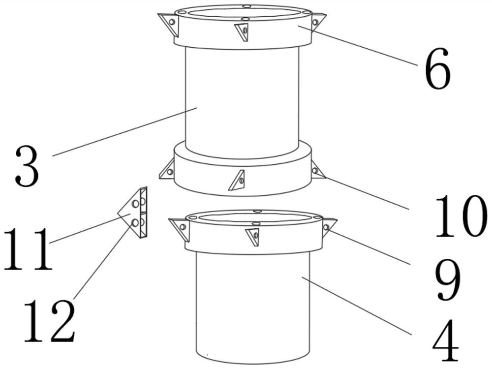
[0039] A mid-suction gasification furnace, such as Figure 1 to Figure 4 As shown, including a furnace body 1, the furnace body 1 is composed of a garbage cracking layer 2, a high-temperature carbon filter layer 3, a combustion chamber 4 and an ash storage chamber 5, and the upper end outer surface of the garbage cracking layer 2 is fixedl...


PUM


Abstract

The invention discloses a mid-suction gasification furnace, which comprises a furnace body. The furnace body is composed of a garbage cracking layer, a high-temperature carbon filter layer, a combustion chamber and an ashes storage room. The outer surface of the upper end of the garbage cracking layer is fixedly installed. There is a trapezoidal garbage hopper, the high-temperature carbon filter layer is divided into a first carbon layer and a second carbon layer, and the first carbon layer is located on the outer surface of the upper end of the second carbon layer, and the high-temperature carbon filter layer is movably connected to the garbage The lower outer surface of the cracked layer. The present invention can firstly be convenient for centralized storage, cleaning and disassembly, and prevent too much ash from affecting the normal operation of the machine; The airtightness of the furnace is good, and moreover, it can supply water to the inside of the layers in the furnace in time according to the needs, and it is easy to disassemble, and finally it is convenient to switch the position of the induced draft fan, reducing the risk of damage caused by the different heights of the air inlet pipes of each layer. It is inconvenient to operate and saves time and effort.

Description

technical field [0001] The invention relates to the technical field of vaporizers, in particular to a mid-suction vaporizer. Background technique [0002] The widely used garbage cleaning technologies in my country are mainly sanitary landfill, incineration and composting. In the urban waste industrialization treatment technology, the quality of the treatment effect depends on the performance of the treatment device. Gasification furnace is a kind of burning appliance with environmental protection, energy saving and cleanliness, suitable for the use of rural households and township farmers. It plays an important role in garbage cleaning. Due to its structural problems, the existing garbage disposal equipment cannot burn garbage. After dust removal and flue gas filtration, it is difficult to avoid secondary pollution to the air. [0003] In the process of realizing the present invention, the inventor found that at least the following problems have not been solved in the pri...

Claims


Application Information

Patent Timeline
Patent Type & Authority Patents(China)
IPC IPC(8): F23G5/027F23G5/44F23J1/06
CPCF23G5/027F23G5/44F23J1/06
Inventor 吴永生岳寿松张瑞琦
Owner 北京鼎胜投资管理有限公司
Why Eureka
Try Eureka